background image

7-5

7. Schematic Diagram

7-2-3 Scaler, Memory Block

- This Document can not be used without Samsung’s authorization.

GND

5V

RxO3+

RxO1-

RxO1+

RxEC+

RxOC+

RxE0-

RxO3-

RxE3-

GND

RxE3+

NC

5V

RxE2+

DATE

SOUND OUTPUT

I2S Digital INPUT

GND

RxE0+

SOUND INPUT

GPIO CONTROL

PANEL INTERFACE

GPIO CONTROL

2493HM : DELETE

5V

HDMI /DVI INPUT

RxE1-

GND

GND

RxE1+

RxO0-

RxO2-

RxO2+

GND

RxEC-

RxO0+

RxOC-

RxE2-

1uF

C337

R768

3.3UH

100ohm

3.3UH

L301

C347

1uF

VDDP

L300

1uF

C322

R300

4.7Kohm

100ohm

R301

4.7Kohm

XREF

R769

AVDD_ADC

C340

100nF

1

1

1

1

50V

C366

1uF

1

1

1/10W

R341

0ohm

0ohm

R340

1/10W

300ohm

U2541

300ohm

U2542

E

B

C

300ohm

U2544

2SC2412K-Q

Q302
SPEC_STRESS_1

U2546

100ohm

0ohm

R763

1/10W

1/10W

R762

0ohm

0ohm

R760

1/10W

1/10W

R761

0ohm

1/10W

1Kohm

R324

R397

4.7Kohm

C342

1/10W

1Kohm

R312

R327
1Kohm

1/10W

1uF

+2.5V_M

XREF

16V

C310
100nF

R364

1uF

C306

0ohm

R764

1/10W

300ohm

100ohm

R767

AVDD_ADC

AVDD_MPLL

1uF

C338

1uF

+5V_PANEL

C334

390ohm

R376

100ohm

R326

+3.3V_LIVE

C313
1nF
50V

470nF

C316

1

50V

1nF

C311

+5V_PANEL

U2543

2.2Kohm

1Kohm

1

U2545

1

+1.8V_LIVE

1

R765

0ohm

R766

1/10W

+1.8V_LIVE

100ohm

1/10W

R371

10Kohm

R323

4.7Kohm
1/10W

100ohm

4.7Kohm

R305

R386

C307

1uF

AVDD_DVI

100ohm

R317

4.7Kohm

R313

1

2

3

4

5

6

7

8

+5V_MICOM

RA306

10ohm

4.7Kohm

R354

1/10W

R314

150ohm

+2.5V_M

1

100ohm

R384

1

1

4.7Kohm

R320

R319

100ohm

2

100ohm

R393

7

8

5

6

3

4

1

+5V_MICOM

+3.3V_LIVE

RA401

R394

10Kohm

R370

1/10W

100ohm

10uF

C367

R377

100ohm

64

VSSQ

DQ15

65

VSS

66

7

DQ3
DQ4

8

VDDQ

9

DQ10

57

58

VSSQ

DQ11

59

6

VSSQ

60

DQ12

VDDQ

61

62

DQ13

63

DQ14

5

50

NC

51

UDQS

VSSQ

52

NC

53

54

DQ8

VDDQ

55

56

DQ9

42

NC

43

CKE

44

45

CLK

/CLK

46

UDM

47

48

VSS

49

VREF

DQ2

A4

36

A5

37

A6

A7

38

39

A8

DQ1

4

40

A9

41

A11

NC

28

A0

29

VDDQ

3

30

A1

31

A2
A3

32

VDD

33

34

VSS

35

20

/WE

21
22

/CAS

23

/RAS
/CS

24

NC

25
26

BA0

27

BA1
A10/AP

13
14

NC

15

VDDQ

16

LDQS
NC

17
18

VDD

19

NC

2

DQ0

LDM

1

VDD

10

DQ5

11

DQ6
VSSQ

12

DQ7

100nF

C358

IC301

K4D261638I-LC50

100nF

C312

16V

100nF

C352

1uF

C333

100ohm

1uF

C324

R391

R395

4.7Kohm
1/10W

R302

+3.3V_LIVE

100ohm

R385

100ohm

R390

100ohm

R322

100ohm

4

1

2

100ohm

R318

RA402

7

8

5

6

3

RA404

7

8

5

6

3

4

1

2

8

33ohm,5%,1/16W,L,CHIP,8P,TP

1

2

3

4

5

6

7

56ohm

RA305

1

2

3

4

5

6

7

8

16V

C309
100nF

10ohm

RA307

10ohm

R337

R355

56ohm

R338

100ohm

100nF

C351

100nF

C353

L307

AVDD_DVI

C321

3.3UH

1uF

50V

C365

1uF

C331

1uF

1

1

+2.5V_M

1

+3.3V_LIVE

R361

300ohm

1

1/10W

4.7Kohm

R306

100nF

C350

470nF

C386

100nF

C349

2.2Kohm

R373

1/10W

+3.3V_LIVE

1/10W

R372

2.2Kohm

+3.3V_LIVE

FT300

1

A

2

B

VDDP

+3.3V_LIVE

BLM41P600S

4.7Kohm

AVDD_MPLL

SPEC_STRESS_1

E

B

C

R303

1/10W

C401

2SC2412K-Q

Q300

R365

4.7Kohm

10nF

RA400

7

8

5

6

3

4

1

2

4

1

2

1/10W

R388

2.2Kohm

RA403

7

8

5

6

3

R387
10Kohm

1/10W

IN

1

GND

2

OUT

3

GND

1

IC304

KIA7042AF-RTF

1

1

1

2

3

4

5

6

7

8

6

7

8

22ohm

RA301

22ohm

RA302

1

2

3

4

5

1

2

3

4

5

6

7

8

+5V_PANEL

RA303

22ohm

1

1

1

R360

300ohm

C388
470nF

4.7Kohm

R315

R316

4.7Kohm

SPEC_STRESS_1

E

B

C

1Kohm

Q301
2SC2412K-Q

R362

R348

R363

300ohm

100ohm

300ohm

C339

1uF
10V

R392

22pF

XREF

XREF

X300

Q0

Q1

C305

1nF
50V

HC-49/S-SMD(14.31818MHZ)

50V

1uF

C303

C359

50V

1uF

C368

1uF

C325

AVDD_AU AVDD_MEMPLL

C326

1uF

C327

1uF

1Kohm

R366

AVDD_AU

AVDD_MEMPLL

99

VDDC

MGND1

1

AVDD_ADC

91

GPIOF[3]

92

GPIOF[4]

93

GPIOF[5]

94

GPIOF[6]

95

GPIOF[7]

96

GPIOF[8]

97

VDDP

98

GND

84

AUOUTR2

85

AUOUTL

86

AUOUTR

87

AUOUTS

88

GPIOF[0]

89

GPIOF[1]

9

GND

90

GPIOF[2]

77

AUR2

78

AUL3

79

AUR3

8

RX1P

80

AUMONO

81

AUOUTL3

82

AUOUTR3

83

AUOUTL2

7

RX1N

70

AVDD_AU

71

AUL0

72

AUR0

73

AUL1

74

AUR1

75

AUCOM

76

AUL2

62

SIF0P

63

AVDD_SIF

64

SIF1P

65

SIF1M

66

GND

67

AUVRADN

68

AUVRADP

69

AUVREF

55

CVBS1

56

VCOM1

57

CVBS0

58

VCOM0

59

CVBSOUT

6

AVDD_33

60

GND

61

SIF0M

48

C1

49

Y1

5

RX0P

50

C0

51

Y0

52

VCOM2

53

CVBS3

54

CVBS2

40

VSYNC2

41

BIN2P

42

BIN2M

43

SOGIN2

44

GIN2P

45

GIN2M

46

RIN2P

47

RIN2M

33

SOGIN0

34

RIN0M

35

RIN0P

36

AVDD_33

37

GND

38

HSYNC0

39

VSYNC0

4

RX0N

26

GIN1M

27

RIN1P

28

RIN1M

29

BIN0M

3

GND

30

BIN0P

31

GIN0M

32

GIN0P

25

GIN1P

250

DI[14

]

251

DI[15

]

252

VDDP

253

HWRESET

254

XOUT

255

XIN

256

AVDD_

MPLL

242

VDDC

243

GND

244

DI[8]

245

DI[9]

246

DI[10

]

247

DI[11

]

248

DI[12

]

249

DI[13

]

235

DI[2]

236

DI[3]

237

VDDP

238

DI[4]

239

DI[5]

24

SOGIN1

240

DI[6]

241

DI[7]

228

GPIOE[0]

229

ICLK

23

BIN1M

230

IDE

231

IHSYNC

232

IVSYNC

233

DI[0]

234

DI[1]

220

LVB1

M

221

LVB0

P

222

LVB0

M

223

VDDP

224

GND

225

GPIOE[3]

226

GPIOE[2]

227

GPIOE[1]

213

LVB3

P

214

LVB3

M

215

LVBCKP

216

LVBCKM

217

LVB2

P

218

LVB2

M

219

LVB1

P

22

BIN1P

206

LVA1

M

207

LVA0

P

208

LVA0

M

209

VDDP

21

REFM

210

GND

211

NC

212

NC

2

RXCKP

20

REFP

200

LVA3

M

201

LVACKP

202

LVACKM

203

LVA2

P

204

LVA2

M

205

LVA1

P

192

PWM2

193

PWM

3

194

AVDD_

MPLL

195

VDDC

196

VDDP

197

NC

198

NC

199

LVA3

P

185

DIGO[2]

186

DIGO[3]

187

DIGO[4]

188

DIGO[5]

189

DIGO[6]

19

VCLAMP

190

DIGO[7]

191

DIGO[8]

178

INT

179

IRIN

18

RMID

180

VDDP

181

GND

182

VDDC

183

DIGO[0]

184

DIGO[1]

170

SAR2

171

SAR3

172

PWM0

173

PWM1

174

DDCR_DA

175

DDCR_CK

176

DDCA_DA

177

DDCA_CK

163

GND

164

SCK

165

SDI

166

CSZ

167

SDO

168

SAR0

169

SAR1

17

VSYNC1

156

AD[5]

157

AD[6]

158

AD[7]

159

WRZ

16

HSYNC1

160

RDZ

161

ALE

162

VDDP

149

MADR[10]

15

DDCD_CK

150

MADR[11]

151

AD[0]

152

AD[1]

153

AD[2]

154

AD[3]

155

AD[4]

141

MADR[5]

142

MADR[6]

143

MADR[7]

144

VDDM

145

GND

146

VDDC

147

MADR[8]

148

MADR[9]

134

CASZ

135

WEZ

136

MADR[0]

137

MADR[1]

138

MADR[2]

139

MADR[3]

14

DDCD_DA

140

MADR[4]

127

MCLK

128

BADR[1]

129

BADR[0]

13

REXT

130

RASZ

131

GND

132

VDDM

133

AVDD_MEMPLL

12

AVDD_33

120

MDATA[1]

121

MDATA[0]

122

DQS[0]

123

DQM

124

MVREF

125

MCLKE

126

MCLKZ

112

VDDM

113

MDATA[7]

114

MDATA[6]

115

MDATA[5]

116

MDATA[4]

117

VDDM

118

MDATA[3]

119

MDATA[2]

105

MDATA[12]

106

VDDM

107

MDATA[11]

108

MDATA[10]

109

MDATA[9]

11

RX2P

110

MDATA[8]

111

GND

1

RXCKN

10

RX2N

100

DQS[1]

101

MDATA[15]

102

MDATA[14]

103

GND

104

MDATA[13]

MST97889CLD-LF

IC300

3

4

5

6

7

8

10V

10uF

C302

RA304

56ohm

1

2

AVDD_SIF

XREF

R321

4.7Kohm

100nF

C345

C329

1uF

C328

1uF

1uF

C330

+5V_PANEL

R347

300ohm

4.7Kohm

R349

XREF

3

WP#
GND

4

SI

5

6

SCLK

7

HOLD#

8

VCC

MX25L4005M2C-15G

IC303

1

CS#

2

SO

+3.3V_LIVE

+1.8V_LIVE

C355

100nF

R351

100ohm

AVDD_MPLL

+2.5V_M

VDDP

AVDD_SIF

AVDD_DVI

AVDD_SIF

C344

1uF

C332

1uF

AVDD_AU

C346

1uF

1uF

C343

C341

1uF

C360

10uF

10V

1/10W

R9022

22ohm

R352

100ohm

R396

R353

100ohm

AVDD_MEMPLL

XREF

100ohm

1

1

1

+3.3V_LIVE

+2.5V_M

1

1

1

3.3UH

L305

3.3UH

3.3UH

L304

L302

L303

3.3UH

2

E2

3
4

VSS

5

SDA

SCL

6

7

/WC

VCC

8

VDDP

1

IC302

S-24CS08AFJ-TB-1GE

NC

1

NC

1

TP330

1

1

1Kohm
1/10W

XREF

1uF

R325

1uF

C336

C335

GND

4

5

/PBRST

3.3V_TOL

6

7

/3.3V_RST

3.3VIN

8

XREF

XREF

IC205

DS1834AS/T.R

5VIN

1

/5V_RST

2

5V_TOL

3

0ohm

R771

1/10W

1/10W

R770

0ohm

100uF

C400

C373

35V

4.7uF

100nF 16V

C370

C304

22pF

+5V_MICOM

R399

4.7Kohm

R382

1

100ohm

HDCP_RESETN

M_WR_PROTECT

WR_PROTECT

PWM0

PWM1

CHK_DSUB

DDC_CTL

AUDIO_EN

PWM2

HP_SENSE

INV_SOS

CHK_DVI

KEY2

KEY1

CHK_HDMI

POWER_KEY

AMP_EN

HP_EN

MCLKE MCLK- MCLK+ BADR1

BADR0

RASZ

CASZ

WEZ

DQM

MVREF1

SP_ALIN SP_ARIN

HDCP_CONTROL

HDMI_HPD

PANEL_RESET

24V_DET

DDC_SCL_DOUT

DDC_SDA_DOUT

PIVOT1

PIVOT2

A_DIM

AUDIO_MUTE

24V_DET

PIVOT3

PIVOT4

POWER_EN

M_WR_PROTECT

WR_PROTECT

SEL_HDMI

PWM3

PWM_DIM

LED_GREEN

MVREF2

HP_EN

BL_EN

BRT_CTL

BADR1

MCLKE

MVREF2

BADR0

DQM

DQM

DQS1

DQS0

MVREF1

MADDR(6)

MADDR(7)

MADDR(8)

MADDR(9)

MADDR(11)

MDATA(0)

MDATA(0:15)

MDATA(1)

MDATA(2)

MDATA(3)

MDATA(4)

MDATA(5)

MDATA(6)

MDATA(7)

MDATA(8)

MDATA(9)

MDATA(10)

MDATA(11)

MDATA(12)

MDATA(13)

MDATA(14)

MDATA(15)

CASZ

WEZ

MCLK+

MCLK-

RASZ

RXC+

RXC-

SOG_PC

PANEL_EN

MADDR(0:11)

MADDR(10)

MADDR(0)

MADDR(1)
MADDR(2)

MADDR(3)

MADDR(4)

MADDR(5)

DDC_SDA_A

AFT

RX2+

RX2-

RX1+

RX1-

RX0+

RX0-

DQS0

DQS1

SPI_DO
SPI_CZ

SPI_DI

SPI_CK

SCL
SDA

DDC_SCL_A

PC_VSYNC_IN

TEST_ALIN

PC_ALIN

TEST_ARIN

PC_ARIN

MADDR(8)

MADDR(9)

MADDR(10)

MADDR(11)

BLUE_IN

B_GND_S

GREEN_IN

G_GND_S

RED_IN

R_GND_S

PC_HSYNC_IN

MDATA(8)

MDATA(9)

MDATA(10)

MDATA(11)

MDATA(12)

MDATA(13)

MDATA(14)

MDATA(15)

MADDR(0:11)

MADDR(0)

MADDR(1)

MADDR(2)

MADDR(3)

MADDR(4)

MADDR(5)

MADDR(6)

MADDR(7)

SPI_CK

SCL
SDA

MDATA(0:15)

MDATA(0)

MDATA(1)

MDATA(2)

MDATA(3)

MDATA(4)

MDATA(5)

MDATA(6)

MDATA(7)

SPI_CZ
SPI_DO

SPI_DI

Memory Block

Scaler

Summary of Contents for 2493HM - SyncMaster - 24" LCD Monitor

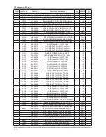
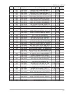
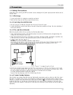
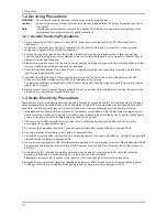
Page 1: ... LCD Monitor Contents 2493HM Refer to the service manual in the GSPN see the rear cover for the more information 1 Precautions 2 Product specifications 3 Disassembly and Reassemble 4 Troubleshooting 5 Exploded View Part List 6 Wiring Diagram 7 Schematic Diagram ...

Page 2: ... 1 4 1 Troubleshooting 4 1 4 2 When the Power Does Not Turn On 4 2 4 3 When a blank screen is displayed Analog 4 4 4 4 When a Blank Screen Is Displayed DIGITAL 4 7 4 5 Error Examples and Actions 4 10 4 6 Adjustment 4 11 5 Exploded View Part List 5 1 5 1 Exploded View 5 1 5 2 Parts List 5 3 6 Wiring Diagram 6 1 6 1 Wiring Diagram Main Board 6 1 6 2 Wiring Diagram Main 6 2 6 3 Wiring Diagram SMPS 6 ...

Page 3: ...urope samsungportal com China http china samsungportal com Asia http asia samsungportal com Mideast Africa http mea samsungportal com This Service Manual is a property of Samsung Electronics Co Ltd Any unauthorized use of Manual can be punished under applicable International and or domestic law 2007 Samsung Electronics Co Ltd All rights reserved Printed in Korea P N BN82 00292A 00 ...

Page 4: ...handling them 3 1 Disassembly Cautions 1 Turn the monitor off before beginning the disassembly process 2 Disassemble the monitor carefully as directed in the following procedures 3 When disassembling the monitor do not use any metal tools except for the provided jig Part Description Picture Description Screws Stand 1 Place the monitor down onto a table covered by a soft cloth and remove the 4 scre...

Page 5: ...tion Picture Description Screws Inverter Cable 3 Seperate the Inverter Cable from the SMPS ASSY CHASSIS 4 Remove the LVDS cable 5 Remove the cable from the SHIELD COVER 6 Remove the cable 7 Remove the hexagonal screws from the bottom of the Shield ...

Page 6: ... and the Speaker Cable from the Main Board Speaker 9 Remove the four 4 screws from both sides of the speakers Decoration 10 Remove the Panel and Chassis separate the Speaker and Function wire from the Decoration and then separate the Decoration Main Board SMPS 11 Remove the 9 screws lift the board and seperate the cable ...

Page 7: ...cription Screws Back Cover 12 Assemble the product in the reverse order of the disassembly When closing the cover close the lower side of the cover first Otherwise the product may be damaged Reassembly procedures are in the reverse order of disassembly procedures ...

Page 8: ...5 1 5 Exploded View Part List 5 Exploded View Part List 5 1 LS24KIERBQ EDC Exploded View T0003 M0112 M0130 M0175 T0175 T0056 M0215 M0014 M0146 T0764 M0006 M0215 M0013 M0003 ...

Page 9: ... COVER DECORATION LS24KIE ABS HB NATURE S 1 S N A T0175 BN96 06426A ASSY SPEAKER P 8ohm kilimanzaro 2W 4p 1w 1 S A M0215 BN07 00399A LCD PANEL LTM240CT01 1 S A T0764 BN44 00195A SMPS LCD MONITOR 245B2 DYREL AC DC 85 67 1 S A M0146 BN63 04051A SHIELD PCB SMPS 2493HM SPTE T0 3 1 S N A M0014 BN94 01549A ASSY PCB MAIN LS24KIEEFV XAA 2493HM 1 S A M0006 BN96 06454A ASSY SHIELD P COVER Kilimanzaro 24 SEC...

Page 10: ...15mm 3m 1 S N A 3 T0069 AA63 60131A SPACER FELT SVP403J FELT BLK T0 5 5 S N A 3 M0006 BN63 04040A COVER REAR 2493HM HIPS HB BK26 1 S N A 0 1 M0216 BN90 01427E ASSY STAND LS24KI USB STAND BLK SPRAY 1 S N A 2 M0003 BN96 06600C ASSY STAND P 2493HM ABS HB BK26_SPRAY US 1 S A 3 T0081 6001 001547 SCREW MACHINE BH M4 L10 5 ZPC BLK SW 4 S A 3 M0081 6003 000275 SCREW TAPTITE BH B M3 L10 ZPC BLK S 4 S N A 3...

Page 11: ...LS27HUB HUBBLE 27 1 S A 2 T0764 BN44 00195A SMPS LCD MONITOR 245B2 DYREL AC DC 85 67 1 S A 2 M0146 BN63 04051A SHIELD PCB SMPS 2493HM SPTE T0 3 1 S N A 2 M0014 BN94 01549A ASSY PCB MAIN LS24KIEEFV XAA 2493HM 1 S A 3 T0245 0202 001608 SOLDER WIRE FLUX LFC7 107 D0 8 99 3Sn 0 0 025 S N A 3 CN102 3701 001173 CONNECTOR DVI 24P 3R FEMALE ANGLE AUF 1 S A 3 CN101 3701 001219 CONNECTOR DSUB 15P 3R FEMALE A...

Page 12: ...2 1 S A 4 ZD111 0403 000258 DIODE ZENER BZX84C5V6 5 2 6V 225mW SOT 2 1 S A 4 ZD500 0403 000258 DIODE ZENER BZX84C5V6 5 2 6V 225mW SOT 2 1 S A 4 D118 0403 000579 DIODE ZENER BZX84C5V1 4 8 5 4V 200mW SOT 1 S A 4 D115 0403 001411 DIODE ZENER 5 49 5 73V 200mW SOD 323 T 1 S A 4 D133 0403 001435 DIODE ZENER QZX363C5V6 5 32 5 88V 200MW 1 S A 4 D0254 0404 001020 DIODE SCHOTTKY BAT54C 30V 200mA SOT 23 T 1 ...

Page 13: ...0 R CHIP 0ohm 5 1 10W TP 1608 1 S A 4 R110 2007 000070 R CHIP 0ohm 5 1 10W TP 1608 1 S A 4 R110 2007 000070 R CHIP 0ohm 5 1 10W TP 1608 1 S A 4 R110 2007 000070 R CHIP 0ohm 5 1 10W TP 1608 1 S A 4 R110 2007 000070 R CHIP 0ohm 5 1 10W TP 1608 1 S A 4 R110 2007 000070 R CHIP 0ohm 5 1 10W TP 1608 1 S A 4 R110 2007 000070 R CHIP 0ohm 5 1 10W TP 1608 1 S A 4 R110 2007 000070 R CHIP 0ohm 5 1 10W TP 1608...

Page 14: ...8 1 S A 4 R110 2007 000074 R CHIP 100ohm 5 1 10W TP 1608 1 S A 4 R110 2007 000074 R CHIP 100ohm 5 1 10W TP 1608 1 S A 4 R110 2007 000074 R CHIP 100ohm 5 1 10W TP 1608 1 S A 4 R110 2007 000074 R CHIP 100ohm 5 1 10W TP 1608 1 S A 4 R110 2007 000074 R CHIP 100ohm 5 1 10W TP 1608 1 S A 4 R110 2007 000074 R CHIP 100ohm 5 1 10W TP 1608 1 S A 4 R110 2007 000074 R CHIP 100ohm 5 1 10W TP 1608 1 S A 4 R110 ...

Page 15: ...110 2007 000084 R CHIP 4 7Kohm 5 1 10W TP 1608 1 S A 4 R110 2007 000084 R CHIP 4 7Kohm 5 1 10W TP 1608 1 S A 4 R110 2007 000084 R CHIP 4 7Kohm 5 1 10W TP 1608 1 S A 4 R110 2007 000084 R CHIP 4 7Kohm 5 1 10W TP 1608 1 S A 4 R110 2007 000084 R CHIP 4 7Kohm 5 1 10W TP 1608 1 S A 4 R110 2007 000084 R CHIP 4 7Kohm 5 1 10W TP 1608 1 S A 4 R110 2007 000084 R CHIP 4 7Kohm 5 1 10W TP 1608 1 S A 4 R110 2007...

Page 16: ...90 R CHIP 10Kohm 5 1 10W TP 1608 1 S A 4 R110 2007 000092 R CHIP 15Kohm 5 1 10W TP 1608 1 S A 4 R110 2007 000093 R CHIP 20Kohm 5 1 10W TP 1608 1 S A 4 R110 2007 000093 R CHIP 20Kohm 5 1 10W TP 1608 1 S A 4 R110 2007 000094 R CHIP 22Kohm 5 1 10W TP 1608 1 S A 4 R110 2007 000094 R CHIP 22Kohm 5 1 10W TP 1608 1 S A 4 R110 2007 000097 R CHIP 47Kohm 5 1 10W TP 1608 1 S A 4 R110 2007 000102 R CHIP 100Ko...

Page 17: ... 1 S A 4 RA401 2011 000881 R NETWORK 33ohm 5 1 16W L CHIP 8P TP 3 1 S A 4 RA402 2011 000881 R NETWORK 33ohm 5 1 16W L CHIP 8P TP 3 1 S A 4 RA403 2011 000881 R NETWORK 33ohm 5 1 16W L CHIP 8P TP 3 1 S A 4 RA404 2011 000881 R NETWORK 33ohm 5 1 16W L CHIP 8P TP 3 1 S A 4 C120 2203 000140 C CER CHIP 1 5nF 10 50V X7R 1608 1 S A 4 C120 2203 000140 C CER CHIP 1 5nF 10 50V X7R 1608 1 S A 4 C120 2203 00014...

Page 18: ...CER CHIP 100nF 10 16V X7R 1608 1 S A 4 C120 2203 005005 C CER CHIP 100nF 10 16V X7R 1608 1 S A 4 C120 2203 005005 C CER CHIP 100nF 10 16V X7R 1608 1 S A 4 C120 2203 005005 C CER CHIP 100nF 10 16V X7R 1608 1 S A 4 C120 2203 005005 C CER CHIP 100nF 10 16V X7R 1608 1 S A 4 C120 2203 005005 C CER CHIP 100nF 10 16V X7R 1608 1 S A 4 C120 2203 005005 C CER CHIP 100nF 10 16V X7R 1608 1 S A 4 C120 2203 005...

Page 19: ...5V 1608 1 S A 4 C120 2203 005065 C CER CHIP 1000nF 80 20 10V Y5V 1608 1 S A 4 C120 2203 005065 C CER CHIP 1000nF 80 20 10V Y5V 1608 1 S A 4 C120 2203 005065 C CER CHIP 1000nF 80 20 10V Y5V 1608 1 S A 4 C120 2203 005065 C CER CHIP 1000nF 80 20 10V Y5V 1608 1 S A 4 C120 2203 005065 C CER CHIP 1000nF 80 20 10V Y5V 1608 1 S A 4 C120 2203 005065 C CER CHIP 1000nF 80 20 10V Y5V 1608 1 S A 4 C120 2203 00...

Page 20: ...8 3 10 1 S A 4 C619 2402 001273 C AL SMD 220uF 20 35V WT REEL 10X10mm 1 S A 4 T0052 2703 001334 INDUCTOR SMD 1 5uH 10 2012 1 S A 4 T0052 2703 001334 INDUCTOR SMD 1 5uH 10 2012 1 S A 4 T0052 2703 001334 INDUCTOR SMD 1 5uH 10 2012 1 S A 4 T0052 2703 001778 INDUCTOR SMD 3 3uH 20 3225 1 S A 4 T0052 2703 001778 INDUCTOR SMD 3 3uH 20 3225 1 S A 4 T0052 2703 001778 INDUCTOR SMD 3 3uH 20 3225 1 S A 4 T005...

Page 21: ...S A 4 R110 2007 000113 R CHIP 33ohm 5 1 10W TP 1608 1 S A 4 R110 2007 000113 R CHIP 33ohm 5 1 10W TP 1608 1 S A 4 R110 2007 000113 R CHIP 33ohm 5 1 10W TP 1608 1 S A 4 R110 2007 000211 R CHIP 1 1Kohm 5 1 10W TP 1608 1 S A 4 C120 2203 000888 C CER CHIP 4 7nF 10 50V X7R 1608 1 S A 4 C120 2203 000888 C CER CHIP 4 7nF 10 50V X7R 1608 1 S A 4 C120 2203 000888 C CER CHIP 4 7nF 10 50V X7R 1608 1 S A 4 C1...

Page 22: ...00397C CBF INTERFACE USB SPL 07 4P 4P 2725 USB2 1 S A 2 M0254 BN96 06445E ASSY ACCESSORY CABLE MANUAL LS24KIERBQ E 1 S A 3 BH68 70448A CARD 01 TFT LCD SRC RUSSIA S W 120 W210 1 S N A 3 T0268 3903 000042 CBF POWER CORD DT EU FP3 YES IEC320 C13 1 S A 3 T0524 6902 000110 BAG PE LDPE T0 05 W250 L400 TRP 28 2 1 S N A 3 T0076 BH68 00633B MANUAL FLYER 02 WARRANTY CARD comm Samsu 1 S N A 3 BN68 00907A MAN...

Page 23: ...5 16 5 Exploded View Part List Memo ...

Page 24: ...onal Standards Institute ANSI C101 1 Leakage Current for Appliances and Underwriters Laboratories UL Publication UL1410 59 7 With the unit completely reassembled plug the AC line cord directly into a 120V AC outlet With the unit s AC switch first in the ON position and then OFF measure the current between a known earth ground metal water pipe conduit etc and all exposed metal parts including metal...

Page 25: ...trument s ground lead last 1 3 Static Electricity Precautions Some semiconductor solid state devices can be easily damaged by static electricity Such components are commonly called Electrostatically Sensitive Devices ESD Examples of typical ESD are integrated circuits and some field effect transistors The following techniques will reduce the incidence of component damage caused by static electrici...

Page 26: ...to turn the power off and unplug the power cord from the outlet before repositioning the product Also check the antenna cable or the external connectors if they are fully unplugged Damage to the cord may cause fire or electric shock Keep the antenna far away from any high voltage cables and install it firmly Contact with the highvoltage cable or the antenna falling over may cause fire or electric ...

Page 27: ...1 4 1 Precautions Memo ...

Page 28: ... Hz 75 Hz Maximum Resolution Horizontal 1920 Pixels Vertical 1200 Pxels Input Signal PC DVI HDMI Input Sync Signal Seperate H V sync Composite automatic synchronization without external switch Level TTL level V high 2 0V V low 0 8V Maximum Pixel Clock Rate 164 MHz Active Display Horizontal Vertical 518 4 H x 324 0 V mm AC Power Voltage Frequency AC 90 264V Volts 60 50Hz Power Consumption Less than...

Page 29: ...Response Time 5ms 5ms Input Source Analog Digital HDMI Analog Digital Magic Color O O Magic Pivot O O Magictune Premium Premium Gamma 3 Step Mode1 Mode2 Mode3 3 Step Mode1 Mode2 Mode3 MagicBright 7 steps Text Internet Game Sports Movie Dynamic CR Custom 7 steps Text Internet Game Sports Movie Dynamic CR Custom Color Tone 4 Step Cool Normal Warm Custom 4 Step Cool Normal Warm Custom ...

Page 30: ... BH68 01387A Samsung Electronics Service center Warranty Card Not available in all locations BH68 00344C User s Guide Monitor Driver Natural Color software MagicTune software BN59 00660A D Sub 15 Pin Cable Shipped as assembled with the set BN39 00244B Power Cord 3903 000085 DVI D Cable BN39 00246F ...

Page 31: ...2 4 2 Product specifications Memo ...

Page 32: ... For DDC 24C02 For DDC 24C02 For DDC 24C32 EEPROM SMPS INVERTER 24V DC DC or Regulator 5V 18V 1 2V 3 3V 5V 9V LVDS Audio Out SOUND AMP TDA 7266 SPEAKER 14 318 MHz 2 5V SCALER MST97889CDL LF SCALER MST97889CDL LF PC ANALOG 180MHz L R L C D P A N E L HDMI HEAD PHONE DDR RAM 128M Serial Flash MX25L4005M DVI HDMI DVI Switch PI3HDMI1210 PC Audio Audio Video 24C02 For DDC 24C02 For DDC 24C02 For DDC 24C...

Page 33: ...4 SDA 5 6 SCL WP 7 8 VCC 24LC02B E SN IC100 1 A0 2 A1 3 A2 D100 1 2 3 1uF C109 XREF 47nF VD C108 C754 0ohm R109 10nF 50V XREF XREF 4 7Kohm R311 1 10W TP_DDCA_SCL 1 5V_DDC_A 100ohm R113 4 1Kohm R345 3 SMAW250 04 WHT CN503 1 2 3 1 D101 1 2 5V_DDC_D 3 3V_LIVE XREF U653 C101 22pF XREF C755 10nF 50V XREF 50V 1 5nF C510 D104 1 TP_DDCA_GND 1 R511 U655 1 TP_DDCA_SDA 1 10Kohm 1 10W 75ohm R124 2 3 1 10W R71...

Page 34: ...EF 1 2 3 4 ZD111 FT104 BZX84C5V6LT1 D133 R272 0ohm XREF 0ohm R276 XREF R1229 4 7Kohm 3 4 7Kohm R147 D107 1 2 B C 1 10W R1145 0ohm 2SC2412K Q Q103 SPEC_STRESS_1 E R149 22ohm 46 D0 A 47 48 D0 A D1 5 D1 6 7 VDD33 SEL 8 D2 9 D0 4 40 VDD33 D3 A 41 42 D3 A 43 D2 A D2 A 44 45 D1 A D1 A VDD33 D3 B 32 D3 B 33 34 D2 B D2 B 35 36 D1 B 37 D1 B D0 B 38 D0 B 39 25 GND 1B2 26 1B1 27 28 OB2 29 0B1 3 D0 GND 30 31 ...

Page 35: ...26 GIN1M 27 RIN1P 28 RIN1M 29 BIN0M 3 GND 30 BIN0P 31 GIN0M 32 GIN0P 25 GIN1P 250 DI 14 251 DI 15 252 VDDP 253 HWRESET 254 XOUT 255 XIN 256 AVDD_MPLL 242 VDDC 243 GND 244 DI 8 245 DI 9 246 DI 10 247 DI 11 248 DI 12 249 DI 13 235 DI 2 236 DI 3 237 VDDP 238 DI 4 239 DI 5 24 SOGIN1 240 DI 6 241 DI 7 228 GPIOE 0 229 ICLK 23 BIN1M 230 IDE 231 IHSYNC 232 IVSYNC 233 DI 0 234 DI 1 220 LVB1M 221 LVB0P 222 ...

Page 36: ...655 2 5V_M 100nF 25V XREF R621 C575 22nF 120Kohm 1 10W 22uF C560 35V 2 5V_M 100nF C662 9 VCC_1 6 15 VCC_2 100nF C661 NC_5 18 2 OUT1 OUT1_ 5 OUT2 19 16 OUT2_ PW_GND_1 1 10 PW_GND_2 PW_GND_3 11 PW_GND_4 20 13 SGND ST_BY 7 IN1 IN2_ 14 8 MUTE NC_1 3 4 NC_2 12 NC_3 17 NC_4 IC500 TDA7266D XREF XREF SPEC_STRESS_1 F601 452 003MRL LEAD FREE 16V C558 47uF 9V C580 100nF 16V 16V 100uF C550 25V 1uF C579 10V 10...

Page 37: ... display as below Resolution 1920 x 1200 H frequency 75 kHz V frequency 60 Hz If no picture appears make sure the power cord is correctly connected Check the following circuits No raster appears Function PBA Main PBA SMPS 5V develop but no screen Main PBA 13V 5V does not develop SMPS Main PBA 1 2 3 ...

Page 38: ... power Check the connection between the SMPS and the Main Board inside the monitor Check the power part of the Main Board and check if a similar symptom appears at another output terminal Diagnostics Main Board Front CN400 CN600 R391 Yes Check the SMPS Board No Is DC 5V measured at pin 15 of CN600 Is a POWER_EN signal measured at pin 16 of CN600 Check the POWER_EN signal of R391 of IC300 Scaler No...

Page 39: ...4 3 4 Troubleshooting 4 2 1 Circuit Diagram and Waveform for Power Failures ...

Page 40: ...ck the signal cables and their connections Yes Check and replace related circuits if necessary No Check if X300 is oscillating normally Check if R G and B inputs are measured at R117 R120 and R121 Check the input part No Yes Check if Hsync and Vsync are measured at R106 and R109 Check the input part No Yes Check if Hsync and Vsync are measured at pins AF12 and E12 of IC300 Check the circuit around...

Page 41: ...4 5 4 Troubleshooting 4 3 1 Circuit diagrams and waveforms analog when a blank screen is displayed on the monitor ...

Page 42: ...4 6 4 Troubleshooting ...

Page 43: ...ctor of the LCD panel Diagnostics Main Board Front CN400 X300 R142 R151 Yes Check the signal cables and their connections Yes Check and replace related circuits if necessary No Check if X300 is oscillating normally Check if R G and B signals are measured at R144 R151 Check the circuit around IC300 No Yes Check if a waveform appears at R142 and R143 Check the input part No Yes Check if the output s...

Page 44: ...4 8 4 Troubleshooting 4 4 1 Circuit diagrams and waveforms DVI when a blank screen is displayed on the monitor ...

Page 45: ...4 9 4 Troubleshooting ...

Page 46: ...nce Symptoms and Actions Remarks Symptom DVI signals are not recognized Cause This error occurs because the PC cannot recognize the mode information since the DVI DDC is not input to the monitor Action Input the DVI DDC On how to input DDC refer to the training manual ...

Page 47: ...he video input 1 For the OSD Language select the language at the top 2 Press and hold the OSD Enter Source for 5 seconds 4 6 2 Firmware Download You have to complete the post operation using a MICOM Jig RS232 Jig after replacing the Main Board You can update the Micom using a MICOM Jig RS232 Jig Requirements The following devices are required for adjusting the monitor A Computer with Windows 95 98...

Page 48: ...4 12 4 Troubleshooting Entering the Micom Code 1 Run winDDC 2 Click Load File and select the latest code in the format of hex ...

Page 49: ...ting 3 Click Program Entering the EDID You can update the EDID DDC Analog DVI HDMI using the DDC Manager Jig Connect the devices as shown below MTI 2059 DDC Manager Signal Connector Connect to the Monitor D SUB DVI HDMI ...

Page 50: ...To exit from the SVC Function OSD you have to turn the power off Panel Information Software Version Checksum The SVC Function OSD consists of a 103 Horizontal x 82 Vertical Grid The SVC Function OSD consists of Panel Information the Software Version and the Micom Checksum Navigating Menus 1 Press the key to move up and press the key to change the value of a selected ...

Page 51: ... and hold the MENU key for 5 seconds The Panel Ch No increases by 1 and the Panel On Time is reset to 0 At the same time the Panel Cycle is also reset to 0 Other Functions 1 Auto Auto On Off 2 PixelShift On Off 3 Country English Korean Chinese Japanese 4 HDCP HP DVI On Off 5 HDCP HP HDMI On Off 6 HotPlug Time 5 50 Default 9 0 9sec ...

Page 52: ...ing the EDID 1 Install the Winddc exe program onto the PC 2 Click the Winddc icon 3 Select Open 4 Select Port 1 5 Open a DDC file File Name SM2493HMA ddc Analog DDC SM2493HMD ddc Digital DDC SM2493HMH ddc HDMI DDC 6 Click Next OK ...

Page 53: ...4 17 4 Troubleshooting 7 Enter the Monitor S N and press Enter Enter for Analog Digital and HDMI ...

Page 54: ...4 18 4 Troubleshooting Memo ...

Page 55: ...6 1 6 Wiring Diagram 6 Wiring Diagram 6 1 Wiring Diagram Main Board CN400 CN600 CN601 CN702 CN101 CN102 CN703 ...

Page 56: ...6 2 6 Wiring Diagram 6 2 Wiring Diagram Main CN703 CN702 ...

Page 57: ...6 3 6 Wiring Diagram 6 3 Wiring Diagram SMPS ...

Page 58: ...6 4 6 Wiring Diagram 6 4 Wiring Diagram PANEL ...

Page 59: ... delivers the LVDS signal from the Main Board to the Panel CN600 It provides 5V and 18V power from the SMPS to the Main Board Symptom No Power CN601 It provides PWM output from the Main Board to the SMPS Symptom No Power or Blank Screen CN500 Audio Input Port Symptom No Audio Output CN501 Audio Output Port Symptom No Audio Output for the Connected External Device 6 6 Cables Use Power Cable Power C...

Page 60: ...6 6 6 Wiring Diagram Memo ...

Reviews: