


4-11
4. Troubleshooting
4-6. Adjustment
4-6-1. Service Adjustment Conditions
Precautions before a Service Adjustment.
1) Check whether the devices for the service adjustment are operating normally.
2) Secure a space that is sufficiently wide for disassembling the monitor.
3) Prepare a soft mat on which the monitor will be disassembled.
Entering Service Mode.
Entering:
Menu
Brightness 0
Contrast 0
Hold down the Enter button for five (5)
Exiting:
Power OFF
Power ON
Auto Color Adjustment
Use a 16 gray-scale or gray-black-mixed pattern for the video input.
1) For the OSD Language, select the language at the top..
2) Press and hold the OSD “(Enter/Source)” for 5 seconds.
4-6-2. Firmware Download
You have to complete the post-operation using a MICOM Jig (RS232 Jig) after replacing the Main Board.
You can update the Micom using a MICOM Jig (RS232 Jig).
Requirements
The following devices are required for adjusting the monitor
A Computer with Windows 95, 98, 2000, XP or NT.
MTI-2059 DDC Manager Jig
-RS232 Jig
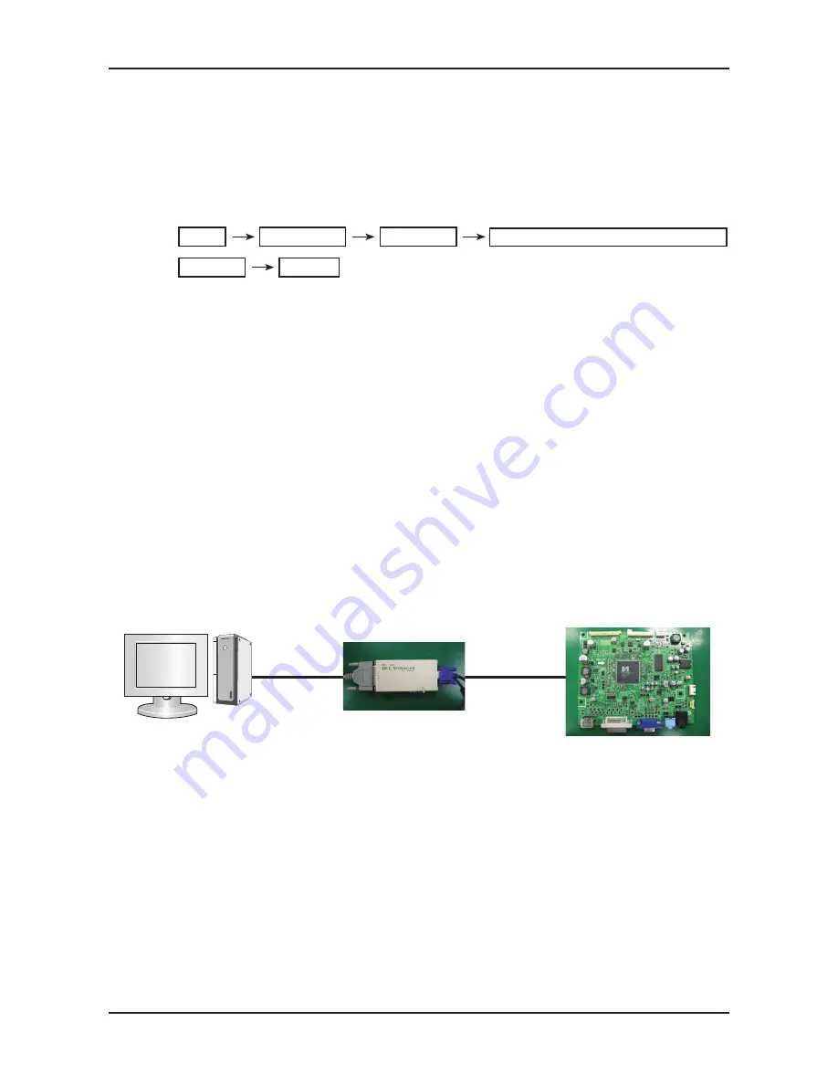
Entering the Micom Code
You have to complete the operation using the DDC Manager after replacing the Main Board.
Connect devices as shown below.
You can update the Micom using the DDC Manager.
1.
2.
3.
-
-
-
-
-
-
-
Connect to the Parallel Board
DDC Manager
RS232 JIG
Connect to the Main Board (CN101)
Summary of Contents for 2493HM - SyncMaster - 24" LCD Monitor
Page 23: ...5 16 5 Exploded View Part List Memo ...
Page 27: ...1 4 1 Precautions Memo ...
Page 31: ...2 4 2 Product specifications Memo ...
Page 39: ...4 3 4 Troubleshooting 4 2 1 Circuit Diagram and Waveform for Power Failures ...
Page 42: ...4 6 4 Troubleshooting ...
Page 45: ...4 9 4 Troubleshooting ...
Page 54: ...4 18 4 Troubleshooting Memo ...
Page 56: ...6 2 6 Wiring Diagram 6 2 Wiring Diagram Main CN703 CN702 ...
Page 57: ...6 3 6 Wiring Diagram 6 3 Wiring Diagram SMPS ...
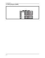
Page 58: ...6 4 6 Wiring Diagram 6 4 Wiring Diagram PANEL ...
Page 60: ...6 6 6 Wiring Diagram Memo ...


