background image

Follow these safety, servicing and ESD precautions to prevent damage and to protect against potential hazards such as 

electrical shock.

1-1-1. Warnings

WARNING

For continued safety, do not attempt to modify the circuit board.
Disconnect the AC power and DC power jack before servicing.

1-1-2. Servicing the LED TV

When servicing the LED TV,  Disconnect the AC line cord from the AC outlet.

1. 

It is essential that service technicians have an accurate voltage meter available at all times. Check the calibration of this 

2. 

meter periodically.

1-1-3. Fire and Shock Hazard

Before returning the monitor to the user, perform the following safety checks:

Inspect each lead dress to make certain that the leads are not pinched or that hardware is not lodged between the 

1. 

chassis and other metal parts in the monitor.
Inspect all protective devices such as nonmetallic control knobs, insulating materials, cabinet backs, adjustment and 

2. 

compartment covers or shields, isolation resistorcapacitor networks, mechanical insulators, etc.
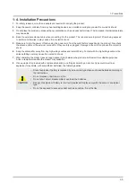
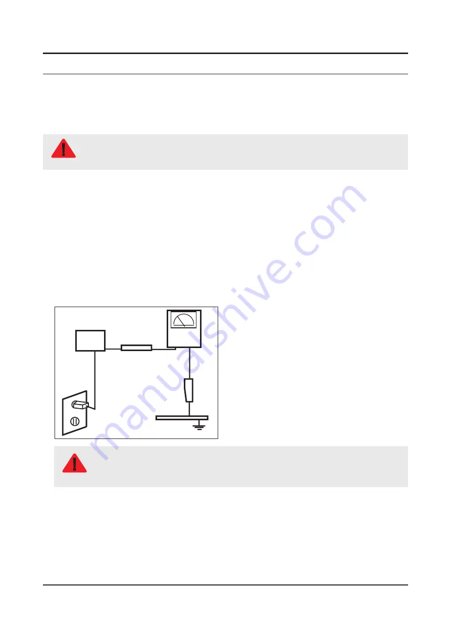
Leakage Current Hot Check:

3. 

DEVICE 

UNDER 

TEST

(READING SHOULD) 

NOT BE ABOVE 0.5mA

LEAKAGE 

CURRENT 

TESTER

TEST ALL 

EXPOSED METAL 

SURFACES

2-WIRE CORD

ALSO TEST WITH 

PLUG REVERSED 

(USING AC ADAPTER 

PLUG AS REQUIRED)

EARTH 

GROUND

WARNING

Do not use an isolation transformer during this test.
Use a leakage current tester or a metering system that complies with American National Standards 

Institute (ANSI C101.1, Leakage Current for Appliances), and Underwriters Laboratories (UL 

Publication UL1410, 59.7).

With the unit completely reassembled, plug the AC line cord directly into a 120V AC outlet. With the unit’s AC switch first 

4. 

in the ON position and then OFF, measure the current between a known earth ground (metal water pipe, conduit, etc.) 

and all exposed metal parts, including: metal cabinets, screwheads and control shafts.  

The current measured should not exceed 0.5 milliamp.  

Reverse the power-plug prongs in the AC outlet and repeat the test.

1-1

1. Precautions

1. Precautions

1-1. Safety Precautions

Summary of Contents for 55JU7000 Series

Page 1: ... UHD TV Contents 1 Precautions 2 Product specifications 3 Disassembly and Reassembly 4 Troubleshooting 5 Wiring Diagram UN JU7100F Chassis UWJ50 Model UN40JU7100F UN50JU7100F UN55JU7100F UN60JU7100F UN65JU7100F UN75JU7100F ...

Page 2: ...ns 2 4 2 3 Accessories 2 8 2 4 Viewing the Functions 2 9 2 5 NEW Key Features 2 11 2 5 1 15 New UI 2 11 2 5 2 Multi Screen 2 12 2 5 3 Instant On 2 13 2 6 HDMI 60P Mode 2 14 2 7 Supported Formats 2 15 3 Disassembly and Reassembly 3 1 3 1 Disassembly and Reassembly 3 1 3 1 1 TV Disassembly 3 1 3 1 2 One Connect MINI 3 5 4 Troubleshooting 4 1 4 1 Troubleshooting 4 1 4 1 1 Previous Check 4 1 4 2 How t...

Page 3: ...4 22 4 4 1 Calibration 4 22 4 4 2 Service Adjustment 4 22 4 4 3 Adjustment 4 24 4 5 RS 232C 4 25 4 6 AV Control Tabe 4 26 4 7 Updating the TV s Software 4 32 5 Wiring Diagram 5 1 5 1 Wiring Diagram 5 1 5 2 Connector 5 3 ...

Page 4: ...anual is a property of Samsung Electronics Co Ltd Any unauthorized use of Manual can be punished under applicable International and or domestic law 2015 Samsung Electronics Co Ltd All rights reserved Printed in Korea ...

Page 5: ...s adjustment and 2 compartment covers or shields isolation resistorcapacitor networks mechanical insulators etc Leakage Current Hot Check 3 DEVICE UNDER TEST READING SHOULD NOT BE ABOVE 0 5mA LEAKAGE CURRENT TESTER TEST ALL EXPOSED METAL SURFACES 2 WIRE CORD ALSO TEST WITH PLUG REVERSED USING AC ADAPTER PLUG AS REQUIRED EARTH GROUND WARNING Do not use an isolation transformer during this test Use ...

Page 6: ...ed by replacing them with components rated for higher voltage wattage etc Parts that have special safety characteristics are identified by on schematics and parts lists A substitute replacement that does not have the same safety characteristics as the recommended replacement part might create shock fire and or other hazards Product safety is under review continuously and new instructions are issue...

Page 7: ... used 2 The internal wiring is sometimes clamped to prevent contact with thermally hot components Reinstall all such elements to their original position After servicing always check that the screws components and wiring have been correctly reinstalled Make sure that 3 the area around the serviced part has not been damaged Check the insulation between the blades of the AC plug and accessible conduc...

Page 8: ...s sufficient to damage ESDs 3 Use only a grounded tip soldering iron to solder or desolder ESDs 4 Use only an anti static solder removal device Some solder removal devices not classified as anti static can generate 5 electrical charges sufficient to damage ESDs Do not remove a replacement ESD from its protective package until you are ready to install it Most replacement ESDs 6 are packaged with le...

Page 9: ...antenna far away from any high voltage cables and install it firmly Contact with the highvoltage cable or the 6 antenna falling over may cause fire or electric shock When installing the product leave enough space 0 4m between the product and the wall for ventilation purposes 7 A rise in temperature within the product may cause fire If an equipment is provided with a replaceable battery and if repl...

Page 10: ... 535 6 X 66 8 mm With stand 917 7 X 587 7 X 271 7 mm 50 Body 1128 8 X 654 3 X 67 4 mm With stand 1128 8 X 706 8 X 277 7 mm 55 Body 1242 6 X 718 3 X 67 4 mm With stand 1242 6 X 770 5 X 277 7 mm 60 Body 1363 6 X 789 3 X 68 2 mm With stand 1363 6 X 838 9 X 295 1 mm 65 Body 1463 4 X 844 2 X 68 8 mm With stand 1463 4 X 897 0 X 295 1 mm 75 Body 1688 8 X 971 0 X 70 2 mm With stand 1688 8 X 1035 8 X 325 0...

Page 11: ...10 4 Kg 50 Body 12 5 Kg With stand 15 3 Kg 55 Body 15 4 Kg With stand 18 2 Kg 60 Body 21 4 Kg With stand 25 6 Kg 65 Body 23 9 Kg With stand 28 1 Kg 75 Body 37 2 Kg With stand 42 9 Kg Panel Type Ultra Clear Pro Internal Memory 8GB DDR DDR3 2 5GB Feature Media Play Movie Photo Music ...

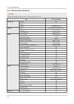
Page 12: ...izontal 60 kHz 73 kHz Automatic Vertical 47 Hz 63 Hz Automatic Display Colors 16 7M color Display Resolution 3840 X 2160 Input Signal Analog 0 7 Vp p 5 positive at 75Ω internally terminated Input Sync Signal H V Separate TTL P or N Maximum Pixel Clock Rate 74 25MHz AC Power Voltage Frequency AC110 120V 60Hz Environmental Considerations Operating Temperature 50 F 104 F 10 C 40 C Operating Humidity ...

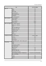
Page 13: ...io Mega Contrast Micro Dimming UHD Dimming Precision Black Local Dimming Precision Black Nano Crystal Color N A Wide Color Enhancer Plus Yes PurColor Yes Auto Depth Enhancer N A Contrast Enhancer Yes Auto Motion Plus Yes Film Mode Yes Natural Mode Support Yes Peak Illuminator Peak Illuminator Audio Dolby Digital Plus Yes MS11 Virtual Surround DTS Studio Sound DTS Codec DTS Premim Sound 5 1 3D Soun...

Page 14: ...oring Yes RVU Yes Samsung SMART View Yes Wireless TV On WOL Yes Notification BLE Yes Briefing On TV Yes WiDi N A WiFi Direct Yes Tuner Broadcasting Digital Broadcasting ATSC Clear QAM 2 Tuner N A CI CI 2CI N A Analog Tuner Yes MHP MHEG HbbTV ACAP GINGA OHTV N A Connectivity HDMI 4 USB 3 Component In Y Pb Pr 1 Composite In AV 1 Ethernet LAN Yes Headphone N A Audio Out Mini Jack Yes Digital Audio Ou...

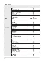
Page 15: ...N A Stand Type Slim T Stand Swivel Left Right N A Additional Feature Samsung 3D Yes 3D Converter Yes Instant On Yes Camera Built in N A Wireless Copy N A Processor Quad Core PX Ready N A 21 9 Immersive Picture Mode N A SCSA Support Yes Accessibility Voice Guide Enlarge High Contrast Digital Clean View Yes One Connect Jack Yes Auto Channel Search Yes Auto Power Off Yes BD Wise Plus Yes Caption Subt...

Page 16: ... Eco Mark Energy Star 6 1 Eco Sensor Yes Lead Presence Yes Accessory 3D Active Glasses Included N A Remote Controller Model TM1560A Batteries for Remote Control Yes Samsung Smart Touch Control Included Yes PX Included N A Ultra Slim Wall Mount Supported N A Mini Wall Mount Supported Yes Vesa Wall Mount Supported Yes Floor Stand Support Yes TV Camera Included N A IR Extender Cable Included N A Wire...

Page 17: ...hased separately The part code for some accessories may differ depending on your region Product Code No Product Code No Smart Touch Control BN59 01220J Power Cord 3903 000985 Batteries AA x 2 4301 000101 User Manual BN68 06967A Image Product Code No One Connect Mini BN96 35817G One Connect Mini Cable BN39 02015A Component adapter BN39 01154C AV adapter BN39 01154H ...

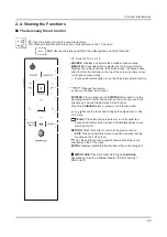
Page 18: ...tton and move the Samsung Smart Control The pointer on the screen moves in the direction you moved the Samsung Smart Control Press the POINTER button to select or run a focused item Enter Press this button to select or run a focused item Press and hold this button to launch the Guide while you are watching the TV RETURN Press this button to return to the previous menu EXIT Press and hold this butt...

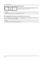
Page 19: ...NOTE The Samsung Smart Control can only be paired to one TV at a time Using the SOURCE button to switch between video sources Press the SOURCE button to switch between external devices connected to the TV For example to switch to a game console connected to the second HDMI connector press the SOURCE button The Source list appears across the top of the screen From the Source list select HDMI2 NOTE ...

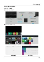
Page 20: ...2 11 2 Product specifications 2 5 NEW Key Features 2 5 1 15 New UI SMART HUB START After Smart HUB setup Videos contents My Apps Web browser My contents ...

Page 21: ... from the Options menu This initializes the selected feature 2 NOTE Features supported by Multi Link Screen very depending on the country TV Video clip TV Web search TV App TV TV dual tuner only Using Multiple Functions in a Single Screen Multi Link Screen Menu Picture Open Multi Link Screen This function may not be available depending on the country or region This allows you to search the Web use...

Page 22: ...2 Product specifications 2 5 3 Instant On Enabling the TV to Boot Faster MENU System General Samsung Instant On Set Fast Boot on to have the TV boot up faster Cold Boot Detachable power Instant On Remocon on ...

Page 23: ...the external UHD player that is connected to the TV 1 Navigate to 2 Picture Picture Options HDMI UHD 60P MODE and set the UHD connected HDMI connector to On When done turn on the external UHD player 3 NOTE After setting the HDMI connector to On It takes some time to complete the conversion HDMI UHD 60P MODE is specific to a UHD source and does not operate properly for any other source If you want ...

Page 24: ... OGG Vorbis Supports up to two channels wma WMA WMA WMA 10 Pro supports up to 5 1 channels WMA lossless audio is not supported Supports up to M2 profile wav wav wav mid midi midi midi Type 0 type 1 and supported ape ape ape Sound or video may not work if they have standard bit rates frame rates above the TV s compatibility If the Index Table is wrong the Seek Jump function does not work When playi...

Page 25: ...soft MPEG 4 v1 v2 v3 Window Media Video v7 WMV1 v8 WMV2 Window Media Video v9 VC1 MPEG2 MPEG1 VP6 H 263 Sorrenson MVC 60 webm WebM VP8 1920x1080 6 30 20 Vorbis Other Restrictions NOTE Codecs may not function properly if there is a problem with the content data Video content does not play or does not correctly if there is an error in the content or container Sound or video may not work if they have...

Page 26: ...mponents 3 1 Disassembly and Reassembly CAUTION Disconnect the LED TV from the power source before disassembly 1 Follow these directions carefully never use metal instruments to pry apart the cabinet 2 If there is no additional coment it is same for all inches 3 3 1 1 TV Disassembly Description Picture Description Screws 1 Place TV face down on cushioned table 2 Remove 4 screws from the ASSY STAND...

Page 27: ... 6003 000003 50 65 75 6003 001782 60 4 Remove the ASSY COVER P REAR 5 Remove the Electric tapes shown on the image EMI Point After removing release paper from the LVDS Cable bottom attach the LVDS Cable to the C Chassis and rub the attatched surface CAUTION When assembling the TV the electric tapes must be applied on the same locations Please remember to take a picture of where the tapes were firs...

Page 28: ... and ASSY BOARD P FUNCTION ASSY Cable LVDS Cable LVDS Cable ASSY BOARD P FUNCTION ASSYCable Panel Wire Cable Remove the NETWORK BT WIFI COMBO Cable NETWORK BT WIFI COMBO Cable 7 Remove the screws of ASSY PCB MAIN and DC VSS LED TV PD BD ASSY PCB MAIN 4 EA DC VSS LED TV PD BD 5 EA 40 50 55 75 6 EA 60 65 NOTE LVDS Cable Torque 7 8Kgf cm 6001 003016 8 Remove the ASSY SPEAKER L R ASSY SPEAKER L R ...

Page 29: ...gf cm 6001 003075 10 Remove the NETWORK BT WIFI COMBO Remove the NETWORK BT WIFI COMBO unit by moving it from left to right 11 Remove the IR unit Remove the IR unit by moving it from up to down IR Assy 12 Remove the JOG unit Remove the JOG unit by moving it from bottom to top 13 Completed disassembly Panel NOTE Reassembly procedures are in the reverse order of disassembly procedures ...

Page 30: ...Connect MINI Description Picture Description Screws 1 Remove 4 Screws from the bottom of the One Connect MINI Torque 7 8Kgf cm 6003 000282 2 Lift off the Bottom Cover NOTE Reassembly procedures are in the reverse order of disassembly procedures ...

Page 31: ...2 How to distinguish if the problem is caused by 3 Main Board or T CON No Video If the problem is No Video but BLU is on and Indication LED is blinking repeatedly and faster than nomal booting replace the T CON board Distorted Picture Check the inner patterns Check list for initial operation 40 55 65 inch Speaker Power Board Power Cable LVDS Cable Bluetooth WIFI Combo Module Main Board T CON Board...

Page 32: ...75 inch Power Board Power Cable Bluetooth WIFI Combo Module Main Board UFP Panel Connectors Jog Function IR Sensor T CON Board LVDS Cable Speaker 4 2 4 Troubleshooting ...

Page 33: ...FRC Pre Test Pattern 3 Verify FRC Post Test Pattern ENTER Factory mode SVC Info Test Pattern T CON FRC 3 FRC Post Test Pattern Main Board HAWK M 1 Scaler Pattern LVDS 4 SoC TCON Test Pattern UFT BOARD 2 FRC Post Test Pattern Not available for UHD Models FRC Pre Test Pattern FRC Post Test Pattern FRC2 Pre Test Pattern FRC2 Post Test Pattern FRC OSD Pre Test Pattern FRC OSD Post Test Pattern SOC TCO...

Page 34: ...tial Start Up Screens with Power On 3 Press Mute 147 Mute to view Test Pattern from the MAIN Board 4 Press Mute 369 Mute to view Test Pattern from T CON Board MAIN Board 12 Start Up Screens 3 Mute 147 Mute 4 Mute 369 Mute T CON Board 4 4 4 Troubleshooting ...

Page 35: ... VERSION Not Support BT Version 3 Check the BT Connector voltage If the DC voltage supply is missing check the cable and the Main Board BT Signal 4V P P Pins 1 2 3 4 5 6 7 8 Standby 0 3 3Vdc 0 5Vdc 0V 0 0 0 Power ON 3 3Vdc 3 3Vdc 0 5Vdc 2V BT Sig 4V P P 2V BT Sig 4V P P 0 Sync 3 3V P P All Measurements in the Chart are DC Volts with Multi Meter Bluetooth Sig Sync Pulse are effective DC Readings Vo...

Page 36: ...rs Model NNNOO0 Wired MAC Wireless MAC WIFI 0000 Wired SUCCESS Wireless SUCCESS 3 Check the Wi Fi Module Connector voltage Wi Fi Signal 500mv P P Pins 9 10 11 12 13 14 15 16 Standby 0 3 3Vdc 0 0 0 5Vdc 0 0 Power ON Sync 3 3V P P 3 3Vdc 0 04Vdc Wi Fi Sig 04Vdc Wi Fi Sig 5Vdc 5Vdc 3 3Vdc All Measurements in the Chart are DC Volts with Multi Meter Voltage is normal but Wi Fi Sig pins DC Ref If you do...

Page 37: ...BT_Wake up O BT Wake up 4 USB DM I O BT USB interface 5 USB DP I O BT USB interface 6 GND GND Ground 7 3D_sync_in I 3D sync input 8 3D_sync_out O 3D sync output 9 Wi Fi GND GND Ground 10 USB DP I O WiFi USB interface 11 USB DM I O WiFi USB interface 12 Vcc I 5V Power 13 Wake up I WiFi Wake up 14 Reset O WiFi Block Reset 4 7 4 Troubleshooting ...

Page 38: ...ept VCC 5V BT nReset Wi Fi nReset WoW ON Wi Fi nReset WoW OFF 3D sync in out BT Power_det Wi Fi USB DP DM BT wake up VCC 5V BT USB DP DM Wi Fi wake up Stand by On state High High High Don t care Don t care 60HZ signal swing 3D mode only 4 8 4 Troubleshooting ...

Page 39: ...i and the TV Panel is OK the disconnect banner will appear 2 Replace defective One Connect Board 3 SYMPTOM When One Connect Mini is connected or disconnected Re boot will be 30 sec later When One Connect Mini is connected or disconnected The Following Message appear on the TV And Re boot will be 30 sec later So Be careful not to disconnected suddenly Arrange the One connect cable with the Cable Ho...

Page 40: ...upported by the TV If you attempt to download an unsupported file you will receive an error message instead The web browser may not be able to access certain websites The TV does not support playback of flash videos E commerce for online purchases is not supported With websites that have scrollable windows scrolling a window can result in corrupted characters ActiveX is not supported Certain optio...

Page 41: ...FLLV1V CY GJ060FLSV1V SMPS BOARD Vendor SEM SEM SEM HANSOE Code BN44 00810A BN44 00811A BN44 00811A BN44 00812A Spec L40S7_FSM L55S7_FSM L55S7_FSM L65S7N_FHS MAIN BOARD Chassis Ass y BN91 14351E BN91 14188B BN91 14351A BN91 14345A PBA Ass y BN94 08410E BN94 08211B BN94 08410A BN94 08298A Byte Item 0 Factory Reset 1 Type 40A1UU7VJ 50A1UU7VJ 55A1UU7VJ 60A1UU7VJ 2 Local set US US US US 3 SW Model UJU...

Page 42: ...SEM Code BN44 00812A BN44 00813A Spec L65S7N_FHS L78S7N_FSM MAIN BOARD Chassis Ass y BN91 14351B BN91 14351J PBA Ass y BN94 08410B BN94 08410J Byte Item 0 Factory Reset 1 Type 65A1UU7VJ 75A1UU7VJ 2 Local set US US 3 SW Model UJU7100 UJU7100 4 BOM Model 7100 7100 5 Tuner S_TC S_TC 6 Ch table NONE NONE 4 12 4 Troubleshooting ...

Page 43: ...TH VER 00XX E MANUAL HMUATSCJ X XXX CAMERA VERSION Not Support BLASTER VERSION Not Support E POP Version HAWKMUD XXXX X EDID SUCCESS HDCP NOT SUPPORT CALIB AV COMP PC HDMI OPTION xxA1UU7WJ US 7100 NONE DTCP Not Support FRC HAWK UFT Panel SDC 120Hz FW 62XX Data 0303 LD BAR 1X5 XX TCON HawkUFT Flash J55A1W0F0 Demura XXXX Model NNNOO0 Wired MAC Wireless MAC WIFI 0000 CO Nf W M D HX P AO O S N RO SC S...

Page 44: ... MRT Option Front Color Engineer Option Control Factory Menu Name Data Range EDID EDID ON OFF Off EDID WRITE ALL EDID WRITE HDMI EDID WRITE PC HDMI EDID Ver HDMI EDID Port Sub Option RS 232 Jack UART RS 232 mode setting EXT Link Support ON Serial Log On Off ON Watchdog ON FRC Monitoring OFF Checksum 0x0000 Fast Boot In Production ON Uart Enable OFF EEPROM RESET ECO IC TYPE MC8121 4 14 4 Troublesho...

Page 45: ...atus OK RM LMN 1ST THRESHOLD 80 LMN 2ND THRESHOLD 60 LMN 3RD THRESHOLD 40 EOS Click OFF BP PMS Reset 1 FAnet Thread 2 User InstantOn Default Value ON CI COLD Version 1 ACM_MC ON HotkeyList 7k_SC UNIQUE TRIPLET ON FS_FAV OFF Private Range USE ON SCSA Support ON OCM Reboot ON SPI Protection ON Hotel Option Hospitality Mode OFF Power On Menu OSD Operation Music Mode External Source Eco Solution Cloni...

Page 46: ...ute automatically Only default on in North America Pilot Level Low THLD 0x10h Carrier2 Amp High ThLD 9 Carrier2 Amp Low THLD 6 Amp Volume 0xc4h Amp Scale 0x9ah The High threshold value of stereo signal If Pilot level is greather than High threshold value recognize Stereo signal Amp EQ Check Sum 0x0165F5A9 The Low threshold value of stereo signal If Pilot level is less than Low threshold value reco...

Page 47: ...UME 0xc9h TP Scale 0x64h TP EQ CheckSum NONE Debug Factory Menu Name Data Range Spread Spectrum DDR Margin BT_ON_OFF ON RF Mute Time 600ms FRC Tuner Margin 3 MPEG Margin 20 H 264 Margin 15 CAM Wait Time 0 European specifications TCON_TEMP READ 62 14 TEMP LAST 6000 DCC VERSION 0x744A DCC CHK SEL 0 DCC CHECK LOCAL 0x811B DCC CHECK TOTAL 0x812B Voice Debug OFF Power Mnangement Cert Option Waiting RM_...

Page 48: ... of T CON eeprom T CON2 Usb Download Failure T CON2 CheckSum PANEL EEPROM UPGRADE Failure PANEL FLASH UPGRADE Failure Logic Usb D L SUBMICOM UPGRADE Ready Upgrade Sub Micom Program SUBMICOM JP USB UPGRADE Ready BT UPGRADE Upgarde BT There is upgrade program in Main Image BT FREEPAIRING ON Function Upgrade Failure FRC3D FW UPGRADE FRC3D LD UPGRADE FRC2 3D FW UPGRADE Camera Upgade Upgarde Camera mod...

Page 49: ...ure SC MBR Upgrade Failure SC MCU Upgrade Failure TCON DEMURA FW UPGRADE NG Reset OPTION_HDMI DVB CI European specifications Test Pattern the Output of test pattern from each IC Other setting SVC Panel ORIGINAL Tizen S N ADC WB Factory Menu Name Data Range ADC AV Calibaration NA Comp Calibration NA PC Calibration NA HDMI Calibration NA ADC Result 1st_Y_GH 255 1st_Y_GL 246 1st_Cb_BH 1st_Cb_BL 1st_C...

Page 50: ...2_R_Offset 128 WB_W2_B_Offset 128 WB_W2_R_Gain 152 WB_W2_B_Gain 78 WB_N_R_Offset 128 WB_N_B_Offset 128 WB_N_R_Gain 142 WB_N_B_Gain 121 MGA MGA On Off OFF R1_Gain 512 G1_Gain 512 B1_Gain 512 R2_Gain 512 G2_Gain 512 B2_Gain 512 R3_Gain 512 G3_Gain 512 B3_Gain 512 R4_Gain 512 G4_Gain 512 B4_Gain 512 R5_Gain 512 G5_Gain 512 B5_Gain 512 R6_Gain 512 4 20 4 Troubleshooting ...

Page 51: ... 512 B6_Gain 512 R7_Gain 512 G7_Gain 512 B7_Gain 512 R8_Gain 512 G8_Gain 512 B8_Gain 512 R9_Gain 512 G9_Gain 512 B9_Gain 512 R10_Gain 512 G10_Gain 512 B10_Gain 512 SPI White Balance SPI MGA WB Data to SPI 0 Advanced 4 21 4 Troubleshooting ...

Page 52: ... Adjust Specification Source Setting Mode Pattern Use Equipment HDMI 1280 x 720 60 Hz Pattern 24 Chess Pattern CA210 Master MSPG925 Generator Chess Pattern Use other equipment only after comparing the result with that of the Master equipment Input mode Calibration Pattern CVBS IN Model_ 1 Perform in NTSC B W Pattern 24 Lattice Component IN Model_ 6 Perform in 720p B W Pattern 24 Lattice PC Analog ...

Page 53: ...h level menu 7 You can see the change of the Comp Calibration status from Failure to Success 8 Method of Color Calibration PC Apply the VESA XGA Lattice N0 21 pattern signal to the PC IN port 1 Press the Source key to switch to PC mode 2 Enter Service mode 3 Select the ADC menu 4 Select the PC Calibration menu 5 In PC Calibration Off status press the key to perform Calibration 6 When Calibration i...

Page 54: ...y Mode 1 Select 2 ADC WB menu Select 3 White Balance menu Option Control Debug SVC ADC WB Advanced White Balance Low Light Sub Brightness R offset G offset B offset Hight Light Sub Contrast R gain G gain B gain 4 24 4 Troubleshooting ...

Page 55: ...ontrol None Description of RS232C Pin Name Full Name Pin Name Full Name Pin Name Full Name 1 CD Carrier Detect 4 DTR Data Terminal Ready 7 RTS Request To Send 2 RxD Received Data 5 GND Signal Ground 8 CTS Clear To Send 3 TxD Transmitted Data 6 DSR Data Set Ready 9 RI Ring Indicator 4 25 4 Troubleshooting ...

Page 56: ... Cmd3 Value Input Source List TV TV 0x0a 0x00 0x00 0x00 AV AV1 0x01 0x00 AV2 0x01 AV3 0x02 S Video S Video1 0x02 0x00 S Video2 0x01 S Video3 0x02 Component Component1 0x03 0x00 Component2 0x01 Component3 0x02 PC PC1 0x04 0x00 PC2 0x01 PC3 0x02 HDMI HDMI1 0x05 0x00 HDMI2 0x01 HDMI3 0x02 HDMI4 0x03 DVI DVI1 0x06 0x00 DVI2 0x01 DVI3 0x02 RVU RVU 0x07 0x00 Control Item Cmd1 Cmd2 Cmd3 Value PICTURE Mod...

Page 57: ...x07 0x00 0x00 Dark 0x01 Darker 0x02 Darkest 0x03 Dynamic Contrast Off 0x01 0x00 Low 0x01 Medium 0x02 HIgh 0x03 Shadow Detail 2 2 0x02 2 2 Gamma 3 3 0x03 3 3 RGB Only Mode Off 0x05 0x00 Red 0x01 Green 0x02 Blue 0x03 Color Space Auto 0x06 0x00 Native 0x01 Custom 0x02 White Balance R Offset LCD 0x07 0 50 White Balance G Offset LCD 0x08 0 50 White Balance B Offset LCD 0x09 0 50 White Balance R Gain LC...

Page 58: ... Space Custom Color Space Custom Color Green Value 0 100 0x14 0 100 Only for active Color Space Custom Color Space Custom Color Blue Value 0 100 0x15 0 100 Only for active Color Space Custom LED Motion Plus Off 0x0a 0x07 0x00 On Normal 0x01 Cinema 0x02 Ticker 0x03 Picture Option Color Tone Cool 0x0a 0x00 0x00 Standard 0x01 Change Normal Standard mode Warm1 0x02 Warm2 0x03 Digital Noise Filter Off ...

Page 59: ... 0x05 Screen Adjustment Picture Size 16 9 0x0b 0x0a 0x01 0x00 Zoom1 0x01 Zoom2 0x02 Wide Fit 0x03 4 3 0x04 Screen Fit 0x05 Smart View I 0x06 Smart View II 0x07 Auto Wide 0x08 New function of 12 only DVB TV Wide Zoom 0x09 Zoom 0x0a Reset Picture Reset Picture 0x0b 0x0b 0x00 0x00 3D 3D Mode Off 0x0b 0x0c 0x00 0x00 2D 3D 0x01 Side By Side 0x02 Top Bottom 0x03 Line By Line 0x04 Vertical Line 0x05 Chec...

Page 60: ...ualizer Balance 0x01 0x00 0 20 100hz 0x01 0 20 300hz 0x02 0 20 1khz 0x03 0 20 3khz 0x04 0 20 10khz 0x05 0 20 Reset 0x06 0x00 SRS TruSurround HD echo Off 0x02 0x00 0x00 Virtual Surrond echo On 0x01 SRS TruDialog echo Off 0x03 0x00 0x00 Dialog Clarify X9 On 0x01 Preferred Language English 0x04 0x00 0x00 Spanish 0x01 French 0x02 Korean 0x03 Japanese 0x04 Multi Track Sound Mono 0x05 0x00 0x00 Stereo 0...

Page 61: ...Only for korea model Auto 0x01 Control Item Cmd1 Cmd2 Cmd3 Value KEY Key Generation 0x0d 0x00 0x00 refer to table OSD Show Hide Control Show 0x0e 0x00 0x00 0x00 Hide 0x01 Get Status Power On Off 0xf0 0x00 0x00 0x00 Volume 0 100 0xf0 0x01 0x00 0x00 Mute On Off 0xf0 0x02 0x00 0x00 Channel Number 0xf0 0x03 0x00 0x00 Source TV AV HDMI 0xf0 0x04 0x00 0x00 Picture Size 0xf0 0x05 0x00 0x00 3D On Off 0xf0...

Page 62: ...Update while the TV is in Standby Mode CAUTION Do not turn off the TV during the Software Update It may cause the TV to malfunction Online To update your TV using the Online method follow these steps Make sure that your TV is connected to your local network and the Internet The connection can be wired or wireless 1 All video and audio settings return to their default settings after a software upda...

Page 63: ... list On the page that appears scroll down to and then click Downloads 4 Click Firmware in the center of the page 5 Click the ZIP button in the File column Click Send in the first pop up that appears 6 Click Save in the second pop up to download and then save the firmware file to your computer Unzip the zip archive to your computer You should have a single folder with the same name as the zip file...

Page 64: ...en the Background upgrade completed the update will be applied the next time the TV is used NOTE This option requires an Internet connection If you agree to the Smart Hub terms and conditions Auto Update will be set to On automatically If you don t want the TV s software updated automatically set Auto Update Support Software Update Auto Update to Off 4 34 4 Troubleshooting ...

Page 65: ... Diagram 5 1 Wiring Diagram 40 50 55 60 65 SMPS TV Board T Con SPEAKER SPEAKER IR receiver One connectMINI BL LED Function WIFI BT CN801S CNL802A CN501 CN1301 CN500 CN9003 CNM803 CN201 CN2301 CN501 7 5k CN502 7k CN2201 CN1302 CN901 ...

Page 66: ...75 SMPS CN801S CNT804 TV Board CN1301 T Con SPEAKER SPEAKER IR receiver CNM803 CN201 CN2301 CN1302 CN2201 One connectMINI CN901 BL LED CN501 CN501 7 5k CN502 7k CN801 Function UFP CN800 CN803 CNL802A CNL802B CN9003 WIFI BT ...

Page 67: ...501 10 CN2301 LVDS 11 CN201 POWER Connector 12 CN1301 BT WIFI 8 CN1302 IR FUNCTION 9 CN502_7K AUDIO CN501_7 5K AUDIO Main Board Pin Map 1 CN1502_RS 1 DGND 5 N C 2 EXLINK_TX 6 N C 3 EXLINK_RX 7 DGNG 4 N C 2 CN1901 USB 1 A5V_USB1_PW 6 USB1RX _USB30 2 USB _USB30 7 GND 3 USB _USB30 8 USB1TX _USB30 4 GND 9 USB1TX _USB30 5 USB1RX _USB30 ...

Page 68: ... GND 33 OCM_13V_PW 17 HDMI1_RX2 _HDMI 4 CN1201 LAN 1 LAN_TXD _LAN 5 B1 8V_PW 2 B1 8V_PW 6 LAN_RXD _LAN 3 LAN_TXD _LAN 7 N C 4 LAN_RXD _LAN 8 GND 5 CN602 COMPONENT 1 GND 5 TEST_PB 2 COMP_Y_CVBS 6 TEST_PR 3 COMP_PB 7 COMP_PR 4 IDENT_COMP 6 CN603 AV 1 GND 5 TEST_SR 2 AV1_CVBS_IN 6 TEST_SL 3 COMP_AV2_SR_IN 7 COMP_AV2_SL_IN 4 IDENT_VIDEO 7 CN1501 1 GND 5 TEST_SR 2 MAX_IN 6 IDENT_HP 3 MAX_OUT 7 GND 4 TE...

Page 69: ...PW 18 M_F_RX _VBY1 44 PANEL_13V_PW 19 VBY1_GND 45 PANEL_13V_PW 20 M_E_RX _VBY1 46 PANEL_13V_PW 21 M_E_RX _VBY1 47 PANEL_13V_PW 22 VBY1_GND 48 PANEL_13V_PW 23 M_D_RX _VBY1 49 PANEL_13V_PW 24 M_D_RX _VBY1 50 PANEL_13V_PW 25 VBY1_GND 51 PANEL_13V_PW 26 M_C_RX _VBY1 11 CN201 POWER Connector 1 GND 12 ANA_DIMMING 2 GND 13 GND 3 A13V_PW 14 OVD_LEVEL 4 GND 15 A13V_PW 5 A13V_PW 16 GND 6 SW_POWER_OUT 17 A13...

Page 70: ...Board 1 P_DIM_6 4 P_DIM_1 2 P_DIM_2 5 P_DIM_4 3 P_DIM_5 7 P_DIM_3 2 CNM803 to Main TCON Board 1 P_DIM_6 16 GND 2 P_DIM_2 17 GND 3 P_DIM_5 18 OD_LEVEL 4 P_DIM_1 19 FAIL_COUNT 5 P_DIM_4 20 ANA_DIM 6 GND 21 A13V 7 P_DIM_3 22 OD_ON OFF 8 GND 23 A13V 9 A13V 24 BLU_ON 10 GND 25 A13V 11 A13V 26 PS_ON 12 GND 27 A13V 13 A13V 28 GND 14 GND 29 GND 15 A13V 30 GND ...

Page 71: ...A to BLU 1 6 9 3 2 VDRV 10 VDRV 3 5 11 NC 4 VDRV 12 NC 5 NC 13 2 6 NC 14 VDRV 7 4 15 1 8 VDRV 16 VDRV 4 Drive To Panel LEDS 1 6 9 3 2 VDRV 10 VDRV 3 5 13 2 4 VDRV 14 VDRV 7 4 15 1 8 VDRV 16 VDRV 7 P_DIM_3 22 OD_ON OFF 8 GND 23 A13V ...

Page 72: ..._RX2 _ HDMI 11 GND 2 GND 12 HDMI1_RX_CLK _ HDMI 3 HDMI1_RX2 _HDMI 13 CEC 4 HDMI1_RX1 _ HDMI 14 N C 5 GND 15 HDMI1_SCL_DDC 6 HDMI1_RX1 _HDMI 16 HDMI1_SDA_DDC 7 HDMI1_RX0 _ HDMI 17 GND 8 GND 18 HDMI1_5V_PW 9 HDMI1_RX0 _HDMI 19 HDMI1_HOT_PLUG 10 HDMI1_RX_CLK _ HDMI 4 CN302 HDMI2_DVI 1 HDMI2_RX2 _ HDMI 11 GND 2 GND 12 HDMI2_RX_CLK _ HDMI 3 HDMI2_RX2 _HDMI 13 CEC 4 HDMI2_RX1 _ HDMI 14 N C 5 GND 15 HDMI...

Page 73: ...MI4_RX1 _HDMI 16 HDMI4_SDA_DDC 7 HDMI4_RX0 _ HDMI 17 GND 8 GND 18 HDMI4_5V_PW 9 HDMI4_RX0 _HDMI 19 HDMI4_HOT_PLUG 10 HDMI4_RX_CLK _ HDMI 7 CN412 SPDIF 1 BOSTON_SPDIF_ IN 3 DGND 2 B5V_PW 8 CN701 OCM 1 SW_POWER_OUT 18 HDMI1_TX2 _HDMI 2 DGND OCM JACK ID 19 CEC_A5V_PW 3 GND 20 HUB1_D _USB 4 HDMI1_TX_SDA_ DDC 21 HUB1_D _USB 5 HDMI1_TX_SCL_ DDC 22 GND 6 CEC 23 HUB2_D _USB 7 GND 24 HUB2_D _USB 8 HDMI_TX_...

Reviews: