background image

25

Start-Up Procedure

Before connecting the heat pump to the system, a thorough system flush is highly recommended in line with the Building Regulations for England and Wales, 
Part L, 2006.
Using a power flusher, fill the system with a mixture of water and 25-30% glycol, there is no pressure sensor in the unit so it can operate from open vented 
to 3 bar max.

Setting up the cylinder immersion heater

The immersion heater will have it’s own temperature stat and this must be set to 70°C. This is to make sure that the legionella function can reach the 
required temperature and complete it’s weekly cycle.

Powering Up

Before applying power to the indoor and outdoor units, make sure that all the room stats and any other run signals are off.

The sequence of power should be the indoor unit and then the outdoor within a few seconds of each other.
On the first startup, the controller will not show any signs of life, after this the controller will light up and start.
When the controller first starts, you should see 01 on the screen, this will show for 90 seconds. If 01 continues to show then the outdoor unit is not 
powered up.

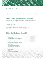
Setting the Clock and Backlight

To alter the date/time, clock and backlight settings on the controller, follow the 
below steps;

1.  Press User Set once, 1 shows on the screen.
2.  Press up until 2 shows.
3.  Press right twice, Year will show, use up to change year Press Set, 

22 appears,

4.  Press right Month will be flashing, adjust Month with up,
5.  Press right, day will be flashing, adjust day with up.
6.  Press Set. 22 shows, press up once, 23 shows,
7.  Press right, day and time are shown, day will be flashing, use up 

to adjust day,

8.  Press right, AM or PM will be flashing, use up to adjust AM, PM 

or both (24- hour clock)

9.  Press right, hour will flash, press up to adjust hours
10.  Press right, minutes will flash, use up to adjust minutes.
11.  Press Set.
12.  23 shows, Press left 2 flashes, press up twice 4 flashes,
13.  Press right, 4 0511 shows, 05 flashes.
14.  Press up until 30 flashes,
15.  Press Set,
16.  Press ESC to finish and return to normal screen.

Summary of Contents for AE050JXYDEH/EU

Page 1: ...SAMSUNG EHS Air Source Heat Pump Installation Guide AE050JXYDEH EU AE090JXYDEH EU AE120JXYDEH EU AE140JXYDEH EU AE160JXYDEH EU Date of Issue 30 01 17 ...

Page 2: ...am 17 Multiple Heat Pumps Heat H W Wiring Diagram 18 Combi Hybrids 19 Combi Hybrid Wiring Diagram 20 Heating Only Hybrids 21 Heating Only Hybrid Wiring Diagram 23 Wiring Power Supply Information 24 What comes with the unit 25 Start Up Procedure 25 Setting up the cylinder immersion heater 25 Powering Up 25 Setting the Clock and Backlight 26 Field Settings 27 Cylinder Timer 28 Electrically testing t...

Page 3: ...m d 75 kg 16 kW Outdoor unit 1420mm h x 940mm w x 330mm d 103 kg Please note that the 12 14 16 kW units are all the same size The clearance around the unit should be as follows 300mm at the back of the unit 300mm at the left hand side of the unit 600mm on the right hand side of the unit to allow access behind the service panel 1500mm from the front of the unit The control box is not designed for o...

Page 4: ...se Existing Pump 25 80 or Bigger 1 1 1 1 2 2 1 1 Flow Meter 40l min 1 1 1 1 1 1 1 1 Magnetic Filter 1 1 1 1 1 1 1 1 Strainer 1 1 1 1 1 1 1 1 Glycol 25 1 1 1 1 1 1 1 1 Inhibitor 1 1 1 1 1 1 1 1 Electrical Isolator 32A 1 1 1 1 2 2 1 1 Fused Spur 16A 1 1 1 1 2 2 1 1 2 Port Valve for Hot Water 28mm 0 0 1 1 1 1 0 0 2 Port Valve for Heating 28mm 0 0 1 1 1 1 1 0 Low Loss Header Buffer or Heat Exchanger 1...

Page 5: ...nits are 5 kW 10 kPa 9 kW 10 kPa 16kW 15 kPa Flow meter 5 kPa Cylinders 5 kPa The best way to overcome the pressure and to achieve the minimum flow rates would be to use one circulation pump size accordingly to the system Flow switch and flow meter Heat pumps have to have a continuous flow rate at all times during operation to check and measure that the flow rate is correct the flow switch that is...

Page 6: ...tself on and off again i e short cycling The introduction of an inverter driven compressor removed this requirement However a hydraulic separator is now used for other things within the system Modulation and Inverters The introduction of inverter driven units with variable speeds meant that the buffer vessel is no longer a requirement for a heat pump system The heat pump changes the speed of the c...

Page 7: ... to as a reduced glycol setup as you can reduce the amount of antifreeze within the system Micro Bore If the heat pump was directly connected to microbore pipe it can prove to be very noisy and will sound like a running tap In order to avoid this a hydraulic separator can be used with this it it possible to have separate flow rates one for the heat pump and one for the micro bore Radiators will ne...

Page 8: ...peration Hot water is controlled using the Samsung cylinder sensor and controller supplied This controller has inbuilt time clock control and includes both a daily and weekly legionella sterilisation function The system can be either open vented or pressurised The cylinder must have a coil at least 2 5m2 Cylinder size normally allows 55l of water per person per day We would recommend sizing the he...

Page 9: ...nnected as well as the immersion heater and the thermostat or a run signal input The 2 core F1F2 cable to the outdoor unit its 10m long and a power supply 16 Amps F1 F2 L N Power Input 16A 15m Tank Sensor Don t shorten Communications Cable 2 core 1mm 16Vdc Immersion Heater Run Signals 240V Power Supply 5kW unit 16A 9kW unit 20A 16kW unit 32A ...

Page 10: ... connected as well as the immersion heater and the thermostat or a run signal input The 2 core F1F2 cable to the outdoor unit its 10m long and a power supply 16 Amps F1 F2 L N Power Input 16A 15m Tank Sensor Don t shorten Communications Cable 2 core 1mm 16Vdc Immersion Heater Run Signals 240V Power Supply 5kW unit 16A 9kW unit 20A 16kW unit 32A ...

Page 11: ...es of water per person each day It is recommended that the heat pump is sized so that it is able to reheat the cylinder within an hour As with most cylinders it is possible to connect a PV system to the immersion heaters to reduce costs A battery storage system is also a great way to help with this The heating system is controlled via a thermostat time clock that is wired back to the internal cont...

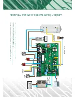
Page 12: ... The other orange and grey wires are not needed The run signal for heating is wired into B20 and B22 B19 is Neutral and B20 is permanently 240V ac Heating Hot Water Systems Wiring Diagram Power Input 16A 15m Tank Sensor Don t shorten 2m Flow Switch Cable Can be extended Run Signal HW H Pump HP Pump Z1 F1 F2 L N Communications Cable 2 core 1mm 16Vdc 240V Power Supply 5kW unit 16A 9kW unit 20A 16kW ...

Page 13: ...t a PV system to the immersion heaters to reduce costs A battery storage system is also a great way to help with this The heating system is controlled via a thermostat time clock that is wired back to the internal control board MIM There is not a limitation to the number of heating zones that can be connected to this setup This setup shows one heating zone Each heating zone will be controlled by i...

Page 14: ...18 Brown and B15 Blue The other orange and grey wires are not needed The run signal for heating is wired into B20 and B22 B19 is Neutral and B20 is permanently 240V ac Power Input 16A 15m Tank Sensor Don t shorten 2m Flow Switch Cable Can be extended Run Signal Cylinder Stat open 55 C H HW Pump HP Pump Z1 F1 F2 L N Communications Cable 2 core 1mm 16Vdc 240V Power Supply 5kW unit 16A 9kW unit 20A 1...

Page 15: ...le to connect a PV system to the immersion heaters to reduce costs A battery storage system is also a great way to help with this The heating system is controlled via a thermostat time clock that is wired back to the internal control board MIM Each heating zone will be controlled by its own thermostat or timer there is no limit to the number of heating zones that can be connected onto this system ...

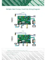
Page 16: ...dependently i e one for upstairs and one for downstairs B20 is permanently 240V AC B19 is Neutral Power Input 3A Remove MCB from unit 2m Flow Switch Cable Can be extended Run Signal Pump HP F1 F2 L N Communications Cable 2 core 1mm 16Vdc 240V Power Supply 5kW unit 16A 9kW unit 20A 16kW unit 32A Power Input 3A Remove MCB from unit 2m Flow Switch Cable Can be extended Pump HP F1 F2 L N Communication...

Page 17: ... B22 on both control boards alternatively you can operate each unit independently i e one for upstairs and one for downstairs B20 is permanently 240V AC B19 is Neutral Power Input 16A Remove MCB from unit 2m Flow Switch Cable Can be extended Run Signal Pump HP F1 F2 L N Communications Cable 2 core 1mm 16Vdc 240V Power Supply 5kW unit 16A 9kW unit 20A 16kW unit 32A Power Input 16A Remove MCB from u...

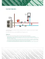
Page 18: ...nd a run signal is sent to the boiler to take over An example of this would be 4 C and this would be when the heat pump s output is lower than the required heat input to the dwelling The heat pump operates when the ambient temperature rises above 5 C and resumes normal operation The renewable heat incentive RHI will be based on the heat provided by the heat pump only a heat meter is needed to moni...

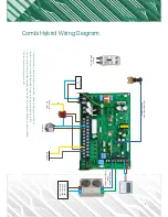
Page 19: ... the Grey to B22 The run signal from the stat and timeclock wire into B22 B19 is Neutral B20 Live permanent 240Vac The run signal for heating wires to B22 F1 F2 L N Power Input 3A Remove MCB from unit 2m Flow Switch Cable Can be extended Communications Cable 2 core 1mm 16Vdc 240V Power Supply 5kW unit 16A 9kW unit 20A 16kW unit 32A Run Signal Run Signal to Combi Pump M B ...

Page 20: ...tly adjusting the water temperature to suit the ambient temperatures and conditions This is the weather compensation of the unit There will need to be a changeover temperature heat pump to boiler for example 3 C When if the ambient temperature falls below the programmed set point a run signal is sent to the boiler to activate the boiler symbol will show and the operation of the heat pump will stop...

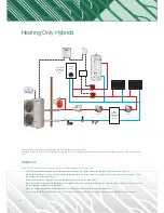
Page 21: ...gnal for the heat pump goes into B20 B22 The run signal for the boiler is B4 Power Input 3A Remove MCB from unit 2m Flow Switch Cable Can be extended Run Signal from Relay Terminal 4 6 Run Signal to Relay Terminal 5 HP1 HP2 F1 F2 L N Communications Cable 2 core 1mm 16Vdc 240V Power Supply 5kW unit 16A 9kW unit 20A 16kW unit 32A ...

Page 22: ...AT PUMP BOILER CYLINDER STAT 28mm ZONE VALVE 28mm ZONE VALVE 230V 50Hz L N E L CH NC C NO M HW NC C NO You will need a relay with DPDT with a 240V coil rated at 5A minimum Instructions Cut the brown wire from stat to heat zone valve Take brown wire from room stat to relay coil 14 Take brown wire from heating 2 port to relay normally open conact Take wire from terminal B4 in Samsung box to relay no...

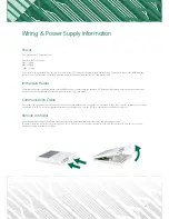
Page 23: ...pur is used it must be labeled so that it is not switched off as this will cause the system to go into a fault Communication Cable The comms cable is used to connect the indoor control box to the outdoor unit The outdoor unit terminals F1 F2 connect to the terminals in the control box labelled F1 F2 To create the signal without issues you should use a 2 core flex 0 5 1mm cable without and breaks o...

Page 24: ... red white and brown cables are used in systems with a backup heater or master slave systems see page 11 These are used to send the run signal from the master over to the slave when needed Using two port valves The two port valve for the cylinder DHW B17 is Brown B15 is Blue and the rest are not needed or used The two port valve for heating is B18 Live and B15 Neutral The heating is controlled wit...

Page 25: ...his the controller will light up and start When the controller first starts you should see 01 on the screen this will show for 90 seconds If 01 continues to show then the outdoor unit is not powered up Setting the Clock and Backlight To alter the date time clock and backlight settings on the controller follow the below steps 1 Press User Set once 1 shows on the screen 2 Press up until 2 shows 3 Pr...

Page 26: ...en set press left twice so that 20 shows pressing the up button will take you to 30 repeat the above process to alter the required settings Once finished press the ESC button to go back to the main menu If your system is used to heat the house enter these settings into the unit 2011 2 low ambient setting for weather comp 5 in Scotland and 3 C for hybrid systems 2012 15 high ambient temp for weathe...

Page 27: ...rs to 0300 7 Press right minutes will be flashing 8 Press right ON will be flashing 9 Press right the tap will appear 10 Press Set You will return to a 2 on the screen repeat the above with a timer at 15 00 hours To adjust or delete the timers enter the timer mode scroll up and down to the timer that needs adjusting press right to the point you wish to adjust change with up and or down press set t...

Page 28: ...symbol that looks like a can will appear pressing the outing button will close the valve again and the symbol disappear If the system is providing heating and is not a hybrid the heating valve should already be open The two port valve for heating is designed to be open when the system is not running Press the set button and this will close the heating valve 2 1 will appear on the screen Press the ...

Page 29: ...air If this doesn t cure the issue then there is something either not right with the system or you need a bigger pump s The unit won t start if the flow rate is not high enough once this has been rectified in heating mode then it s time to test in hot water mode Press the set button to close the heating valve 2 1 will appear on screen Manually open the hot water valve with the lever and lock it no...

Page 30: ... heat pump The tap symbol is the hot water temperature inside the cylinder The flow temperature that is shown by the house within a circle will increase over time and in turn this will start to heat up the heating circuits You can check this by feeling the radiators or checking the temperature of the underfloor heating loops If the compressor doesn t start after 5 minutes then you will need to che...

Page 31: ...anged so that the fluid is flowing through the coil in the cylinder To make sure that you have a gain in the cylinder mark down the current temperature in the cylinder by pressing the oval view button After 15 20 minutes take a look again at the temperature inside the cylinder you should have a rise in temperature from earlier if no gain has occurred check the location of the blue sensor If the he...

Page 32: ...ow temperature depending on the outdoor temperature The colder it is outside the warmer the temperature provided will be and vice versa This is automatic and is designed to save you money In very cold weather the radiators will be at their hottest they will reach 50 C Running your machine efficiently It would prove to be expensive to heat the house up from cold every time you required heat With a ...

Page 33: ...stantly this cannot be stopped Hot Water The temperature of the cylinder is controlled by the Samsung controller this is setup to maintain the temperature of the water between 43 C and 50 C As hot water is used the heat pump will be constantly monitoring the temperature inside the cylinder the hot water heating has priority over space heating If the cylinder falls by 5 C from the setpoint the heat...

Page 34: ...e The warranty is held with Solfex and the heat pump and not the installer or homeowner If the installer wishes to do so they can offer a warranty to you end user that covers the whole system The standard warranty terms for the Samsung heat pump is 3 years if the installer is a Samsung certified installer then the warranty terms are 7 years Once we receive the completed warranty form via our websi...

Page 35: ...button on rc Cylinder water temp after 30mins Press view button on rc Water flow temp From remote controller Water return temp Measure this Flow Rate l min From flow meter Immersion heater current Press immersion button on rc Immersion heater cutout setting Remove cover and adjust to 70 C Commissioning Data not required at maintenance Where was the unit purchased Date installed Date delivered Proo...

Page 36: ...able to see that it is in hot water mode when the can symbol appears The heat pump should be able to reach 48 C without help from the immersion heater Whist the heat pump is running you can start doing other checks Hot water Cylinder To check the cylinder firstly you want to check the immersion connections and make sure that the blue tank sensor is still correctly in place Also make sure that the ...

Page 37: ...roller meaning that the heat pump will only operate when it receives a run signal back to B22 or B24 in the control box The best thing to do is to switch of the stats and run the tests from earlier Hot water If you are noticing a lack of hot water it could be that the tank stat is positioned too low in the cylinder and the immersion heater is on all the time Another possibility is that the cylinde...

Page 38: ...e problem and you will need a new brown PCB 00 shows on the remote controller 00 will show when the MIM board is first powered up this means that the PCB has activated but the outdoor unit is not connected and fault code E201 will appear Check the F1 F2 wiring is good between the outdoor unit and indoor unit also check the power to the outdoor unit 01 shows on the remote controller 01 on the contr...

Page 39: ...rmal position move the paddle and it should measure 0 ohms Ω If moving the paddle does not change the value then it is likely the flow switch is faulty Cold Weather Protection my unit won t start The Samsung heat pump has a variety of cold weather protection functions these are The heat pump will not start if the fluid in the system is 10 C or lower if the sensors within the heat pump detect that ...

Page 40: ...SOLFEX Ltd Energy Arena Units 3 5 Charnley Fold Industrial Estate Bamber Bridge Preston Lancashire PR5 6PS Tel 01772 312 847 Fax 01772 335 277 Email heatpumpsales solfex co uk www solfex co uk ...

Reviews: