23
English
Installation Pr
oc
edur
e
N
N
1-NO 1-NC
N
2-NO 2-NC
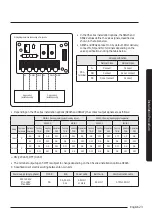
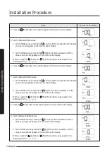
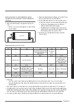
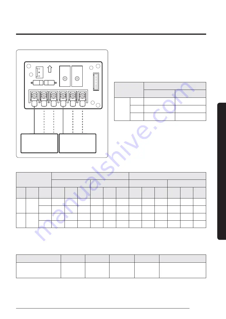
Wiring diagram when connecting a 3-way valve
3-way valve1
(installed on site)
3-way valve2
(installed on site)
• In the 05 series installation options, the SEG15 and
SEG22 values define the valve signals, classified as
shown in the table below.
• SEG15 and SEG22 are set to 0 by default. After delivery,
connect N, NO, and NC terminals depending on the
valve specifications noting the table below:
Valve specification
Normal Close
Normal Open
PBA
terminal
N
Connect
Connect
NO
Connect
Do not connect
NC
Do not connect
Connect
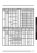
• Depending on the 05 series installation options (SEG15 and SEG22), the contact output signals are as follows:
SEG22: 0 (Cooling/Heating synchronizing signal)
SEG22: 1 (Cooling/Heating signal separated)
SEG15: 0
SEG15: 1
SEG15: 0
SEG15: 1
Valve
Common
terminal
Optional
terminal
Cooling
T-ON
Heating
T-ON
Operation
OFF
Cooling
T-ON
Heating
T-ON
Operation
OFF
Cooling
T-ON
Heating
T-ON
Operation
OFF
Cooling
T-ON
Heating
T-ON
Operation
OFF
Valve 1
N
NO
ON
ON
OFF
OFF
OFF
ON
ON
OFF
OFF
OFF
ON
ON
NC
OFF
OFF
ON
ON
ON
OFF
OFF
ON
ON
ON
OFF
OFF
Valve 2
N
NO
ON
ON
OFF
OFF
OFF
ON
ON
OFF
OFF
OFF
ON
ON
NC
OFF
OFF
ON
ON
ON
OFF
OFF
ON
ON
ON
OFF
OFF
࢘
ON (220 VAC), OFF (0 VAC)
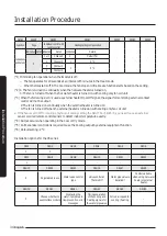
• The terminal output upon T-OFF is subject to change depending on the 05 series installation options, SEG16.
4
Specifications of electrical wiring between fan coil units
Power supply (single phase)
MCCB
ELB
Power cable
Earth wire
Communication cable
220 to 240 V
Min. 198V
Max. 264V
XA
XA, 30 mA
0.1 s
2.5 mm²
or more
2.5 mm²
0.75 to 1.5 mm²
Summary of Contents for AGTN1DKH Series
Page 41: ...41 English Appendix Memo ...
Page 42: ...42 Memo English Appendix ...
Page 43: ...43 English Appendix ...
Page 44: ...DB68 09309A 00 ...

