4-14
Samsung Electronics
Step 1
Review all the following elements in the installation:
◆
Installation site strength
◆
Piping connection tightness to detect any gas leakage
◆
Connection wiring
◆
Heat-resistant insulation of the piping
◆
Drainage
◆
Earthing wire connection
Step 2
IMPORTANT!
Before selecting switch turn off the system power supply
Step 3
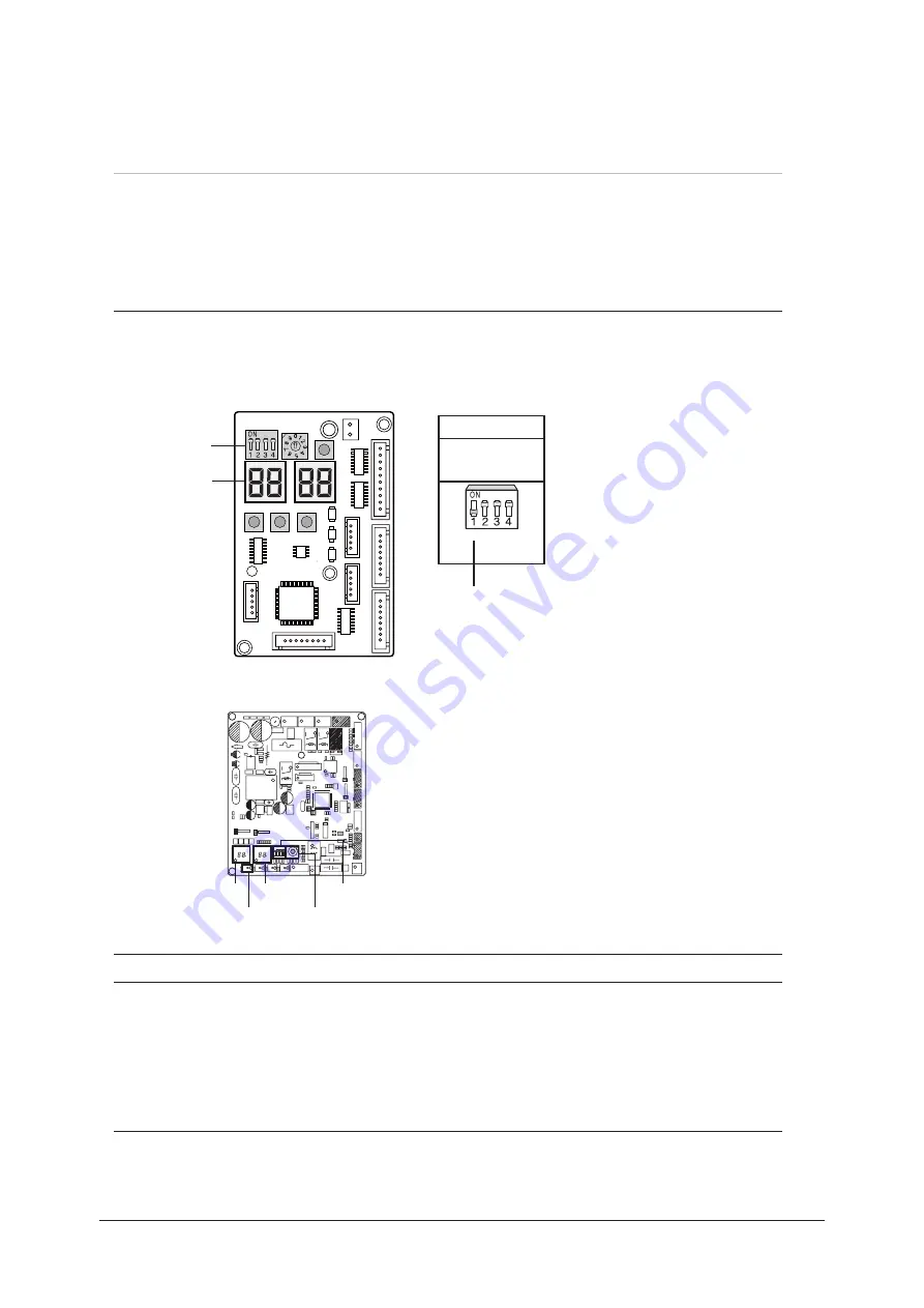
Follow of indication reported into table below for indoor unit addressing
Step 4
Turn on the system power supply and waiting for 60 seconds after estabilishing communication
between outdoor and indoor units.
During this phase, the left display of outdoor unit display PCB “DIS01” will count fom 00--01--02 to 15.
Estabilished communication the left display will count sequentially:
00--communication with indoor unit A;
01--communication with indoor unit B;
02--communication with indoor unit C;
03--communication with indoor unit D;
※
In case of Manual address mode,you can do pipe check operation for check whether you connect the pipes correctly or not.
But you need set indoor address switch yourselves.
Switch
Indoor unit
address
Display of the external unit
SW 02
Manual
addressing
Move down the
switch n°1
- Move dipswitch n°1 of “SW02 - outdoor
unit display PCB” down;
Advise control we are going to proceeed with manual addressing as follow:
Display 1
Display 2
K1
Rotary
Switch
DIP
Switch
AJ036JCJ5CH
AJ020JCJ2CH/AJ024JCJ3CH
4-3-2 Without wiring checking function


