1
3
. Installation
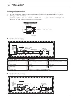
When more than two water pipes are used for heating (e.g. Floor + Fan Coil Unit), Buffer Tank (Mixing Tank) or
bypass valve should be used to maintain the water flow rate.
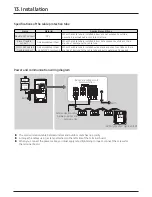
▶ On site installation specification
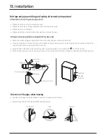
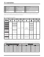
2) Do not exceed the torque value stated in the below table. If you apply more torque, it may cause damage to the
product.
Diameter of water pipe (Outer diameter, mm)
Tightening torque
mm
inch
N·m
lbf·ft
10 ~ 20
0.39 ~ 0.79
25
18.4
21 ~ 30
0.83 ~ 1.18
50
36.9
31 ~ 50
1.22 ~ 1.97
100
73.8
51 ~ 80
2.0 ~ 3.15
220
162.3
81 ~ 115
3.19 ~ 4.53
600
442.5
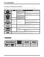
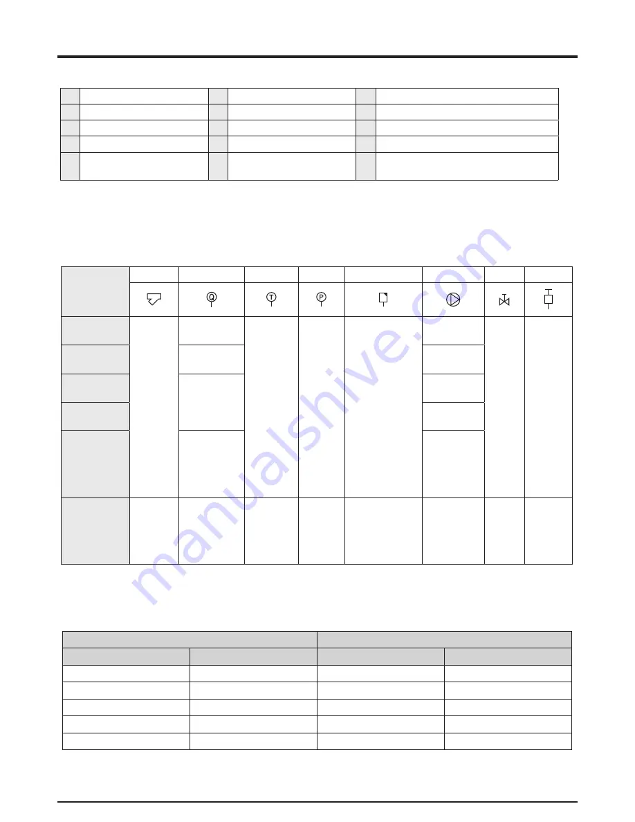
Model name
Strainer
Flow meter Thermometer Manometer
Air vent
Pump
Ball valve Drain valve
AM048CNBFCB
#50 NPT
0~50 ℓ/min
(0 ~ 13 .2 gal/min)
0~100 °C
(0~212 °F)
0 ~ 1 Mpa
(0 ~ 145
psi)
0 .6 m3/h
(158 .5gal/h)
[Condition:
0 .15MPa (21 .8psi)]
23 ℓ/min
(6 .1 gal/min)
NPT 1"
15 A
AM072CNBFCB
0 ~ 100 ℓ/min
(0 ~ 26 .4 gal/min)
36 ℓ/min
(9 .5 gal/min)
AM036CNBDCH
0 ~ 50 ℓ/min
(0 ~ 13 .2 gal/min)
36 ℓ/min
(9 .5 gal/min)
AM048CNBDCH
48 ℓ/min
(12 .7 gal/min)
AM096CNBDCH
0 ~ 100 ℓ/min
(0 ~ 26 .4 gal/min)
92 ℓ/min
(24 .3 gal/min)
(Refer
to
pressure
drop
graph)
AM144CNBDCH
#50 NPT
0 ~ 150 ℓ/min
(0 ~ 39 .6 gal/min)
0 ~ 100 °C
(0 ~ 212 °F)
0 ~ 1 Mpa
(0 ~ 145
psi)
0 .6 m3/h (158 .5 gal/
h) [Condition: 0 .15
MPa (21 .8 psi)]
150 ℓ/min
(39 .6 gal/min)
(Refer
to
pressure
drop
graph)
NPT 1-1/4"
15 A
①
Water pipe joint (union, flange)
⑤
Flexible joint
⑨
Expansion tank
②
Thermometer
⑥
Drain (within the product)
⑩
Temperature sensor for thermal storage tank
③
Manometer
⑦
Pump
⑪
Drain valve
④
Ball valve
⑧
Air vent
⑫
Strainer
⑬
Water Valve
⑭
Pressure relief valve
(Pressure safety valve)
⑮
Differential Pressure bypass Valve


