background image

3

English

Sa

fe

ty

 In

fo

rm

at

io

Safety Information

  WARNING

•  Hazards or unsafe practices that may result in severe 

personal injury or death.

  CAUTION

•  Hazards or unsafe practices that may result in minor 

personal injury or property damage.

•  Carefully follow the precautions listed below because they 

are essential to guarantee the safety of the equipment.

  WARNING

•  Always disconnect the air conditioner from the power 

supply before servicing it or accessing its internal 
components.

•  Verify that installation and testing operations are 

performed by qualified personnel.

•  Verify that the air conditioner is not installed in an 

easily accessible area.

General information

  WARNING

•  Carefully read the content of this manual before 

installing the air conditioner and store the manual in 
a safe place in order to be able to use it as reference 
after installation.

•  For maximum safety, installers should always carefully 

read the following warnings.

•  Store the operation and installation manual in a safe 

location and remember to hand it over to the new 
owner if the air conditioner is sold or transferred. 

•  This manual explains how to install an indoor unit with 

a split system with two SAMSUNG units. The use of 
other types of units with different control systems may 
damage the units and invalidate the warranty. The 
manufacturer shall not be responsible for damages 
arising from the use of non compliant units.

•  The manufacturer shall not be responsible for damage 

originating from unauthorized changes or the 
improper connection of electric and requirements set 
forth in the “Operating limits” table, included in the 
manual, shall immediately invalidate the warranty.

•  The air conditioner should be used only for the applications for 

which it has been designed: the indoor unit is not suitable to 
be installed in areas used for laundry.

•  Do not use the units if damaged. If problems occur, switch 

the unit off and disconnect it from the power supply.

•  In order to prevent electric shocks, fires or injuries, 

always stop the unit, disable the protection switch 
and contact SAMSUNG’s technical support if the unit 
produces smoke, if the power cable is hot or damaged 
or if the unit is very noisy.

•  Always remember to inspect the unit, electric 

connections, refrigerant tubes and protections 
regularly. These operations should be performed by 
qualified personnel only.

•  The unit contains moving parts, which should always 

be kept out of the reach of children.

•  Do not attempt to repair, move, alter or reinstall the 

unit. If performed by unauthorized personnel, these 
operations may cause electric shocks or fires.

•  Do not place containers with liquids or other objects 

on the unit.

•  All the materials used for the manufacture and 

packaging of the air conditioner are recyclable.

•  The packing material and exhaust batteries of the 

remote controller(optional) must be disposed of in 
accordance with current laws.

•  The air conditioner contains a refrigerant that has 

to be disposed of as special waste. At the end of its 
life cycle, the air conditioner must be disposed of in 
authorized centres or returned to the retailer so that it 
can be disposed of correctly and safely.

Installing the unit

  WARNING

IMPORTANT: When installing the unit, always remember 
to connect first the refrigerant tubes, then the electrical 
lines.

•  Always disassemble the electric lines before the 

refrigerant tubes.

•  Upon receipt, inspect the product to verify that 

it has not been damaged during transport. If the 
product appears damaged, DO NOT INSTALL it and 
immediately report the damage to the carrier or 
retailer (if the installer or the authorized technician has 
collected the material from the retailer.)

•  After completing the installation, always carry out a 

functional test and provide the instructions on how to 
operate the air conditioner to the user. 

k}t†⴬㨰䛙†~•‹Tm™ŒŒGXžˆ †pt†lu†ki]_TW^\\WhTWXU•‹‹GGGZ

YWX_TWYTY_GGG㝘㤸GXXaXXa[X

Summary of Contents for AM***NN1DCH series

Page 1: ...manual AM NN1DCH Thank you for purchasing this Samsung air conditioner Before operating this unit please read this manual carefully and retain it for future reference k t 㨰䛙 Tm GX pt lu ki _TW WhTWXU GGGX YWX_TWYTY_GGG㝘㤸GXXaXXa X ...

Page 2: ... Step 7 Connecting the assembly pipes to the refrigerant pipes Step 8 Performing the gas leak test Step 9 Insulating the refrigerant pipes Step10 Installing the drain hose and drain pipe Step11 Performing the drainage test Step12 Connecting the power and communication cables Step13 Optional Extending the power cable Step14 Setting the indoor unit addresses and the installation options Performing f...

Page 3: ...fdamaged Ifproblemsoccur switch theunitoffanddisconnectitfromthepowersupply In orderto prevent electric shocks fires or injuries always stop the unit disable the protection switch and contact SAMSUNG s technical support if the unit produces smoke if the power cable is hot or damaged or if the unit is very noisy Always rememberto inspect the unit electric connections refrigerant tubes and protectio...

Page 4: ...ify that the air conditioner is connected to the power supply in accordance with the instructions provided in the wiring diagram included in the manual Always verify that electric connections cable entry section of leads protections are compliant with the electric specifications and with the instructions provided in the wiring scheme Always verify that all connections complywith the standards appl...

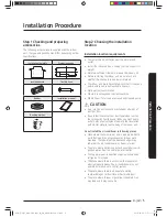
Page 5: ...ned easily CAUTION As a rule the unit cannot be installed at a height of less that 2 5m If you install the cassette or duct type indoor unit on the ceiling with humidity over 80 you must apply extra10mm of polyethylene foam or other insulation with similar material on the body of the indoor unit Do not install the airconditionerin following places Place where there is mineral oil or arsenic acid R...

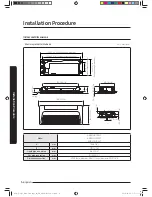
Page 6: ...eiling 1150 45 1 4 Ceiling opening dimension 249 9 11 16 Space of suspension bolts 440 17 5 16 Ceiling opening dimension 1036 40 11 16 Space of suspension bolts Model AM007NN1DCH AM009NN1DCH AM012NN1DCH A mm 130 5 1 8 B mm 179 7 1 16 Liquid pipe connection mm Ø6 35 1 4 Gas pipe connection mm Ø12 70 1 2 Drain hose connection mm VP20 outer diameter Ø26 1 innder diameter 20 13 16 k t 㨰䛙 Tm GX pt lu k...

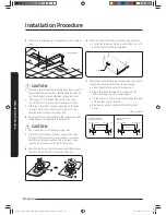
Page 7: ...an extra10mm 3 8 inch thick polyethylene insulation or a similartype of insulation to the body of the indoor unit Cut away the part where pipes are pulled out forthe insulating work Insulate the end of the pipe and some curved area by using separate insulator Step 4 Installing the indoorunit When deciding on the location of the air conditionerthe following restrictions must be taken into account 1...

Page 8: ...o the drainage pipe connection the refrigerant pipe connection orto remove the unit if necessary 5 Hang the indoor unit to the suspension bolts between two nuts Screw the nuts to suspend the unit 1 2 2 6 Check the level of the indoor unit by using a leveler A tilt of the indoor unit may cause malfunction of a built in float switch and water leaks Level 7 Adjust the unit to the appropriate position...

Page 9: ...ge remains at a 90 angle to the side of the pipe Referto the illustrations below for examples of edges cut correctly and incorrectly Pipe cutter Pipe Oblique Rough Burr 3 To prevent any gas from leaking out remove all burrs at the cut edge of the pipe using a reamer 4 Slide a flare nut on to the pipe and modify the flare Pipe Flare D A Flare R 0 4 to 0 8 mm D L 90 2 4 5 2 0 016 to 0 032 inch Outer...

Page 10: ...insulation 4 Make sure that there are no cracks orwaves on the bent area 5 It would be necessary to double the insulation thickness 10 mm 3 8 inch or more to prevent condensation even on the insulatorwhen if the installed area is warm and humid 6 Do not use joints or extensions forthe pipes connecting the indoor and outdoor units The only permitted connections are those forwhich the units are desi...

Page 11: ...e around the pipes and drain hose avoiding compressing the insulation too much 3 Finish wrapping insulating tape around the rest of the pipes leading to the outdoor unit 4 The pipes and electrical cables connecting the indoor unit with the outdoor unit must be fixed to the wall with suitable ducts Insulation cover pipe Insulation pipe Be sure to overlap the insulation Indoor unit CAUTION Must fit ...

Page 12: ...stalling insulation in the places and conditions below use the same insulation that is used for high humidity conditions Geological condition High humidity locations such as shorelines hot springs lake or riversides and ridges when part of the building is covered by earth and sand Operation purpose condition Restaurant ceiling sauna swimming pool etc Building construction condition Ceilings freque...

Page 13: ...le field supply 5 Insulate the whole drain pipe inside the building field supply The whole drain pipe must be insulated with 5t or more insulation to prevent condensation CAUTION Check that the indoorunit is level with the ceiling by using the leveller Install airventilation to drain condensation smoothly Ceiling Airventilation If it is necessary to increase the height of the drain pipe install th...

Page 14: ...pipe Full thread bolt hanger 300 to 550 11 13 16 to 21 5 8 200 7 7 8 ormore Individual airvent Main airvent must be installed Unit mm inch 1 to 1 5 m 3 28 4 92 ft If 3 or more units are installed install the main airvent at the front of the farthest indoor unit from the main drain pipe To prevent waterfrom flowing back to indoorunits install an individual airvent at the top of each indoorunit The ...

Page 15: ... switch is not detected due to insufficient water on the drain pan the drain pump will not work If the power supply is directly connected to the L and N terminals communication error message might appear After completing the drainage check turn the unit off and disconnect the power supply Reassemble the control box cover c Check whetherthe drain pump works correctly d Check whetherthe drainage is ...

Page 16: ... 89 M4 1 2 to1 8 0 89 to1 1 ߢĘࡷ ॉߢߡ ࡷʀ To protect the product from waterand possible shock you should keep the powerand the communication cables of the indoorand outdoorunits in the iron pipe Connect the power cable to the auxiliary circuit breaker ELCB MCCB ELB Keep distances of 50 mm 1 15 16 inch or more between power cable and communication cables Power supply cords of parts of appliances for o...

Page 17: ...6 0 25 8 0 0 31 6 6 0 25 8 5 0 33 9 5 0 37 Allowance mm inch 0 2 0 007 0 2 0 007 0 2 0 007 D Standard dimension mm inch 3 4 0 13 4 2 0 16 5 6 0 22 Allowance mm inch 0 3 0 011 0 2 0 007 0 3 0 011 0 2 0 007 0 3 0 011 0 2 0 007 d1 Standard dimension mm inch 1 7 0 06 2 3 0 09 3 4 0 13 Allowance mm inch 0 2 0 007 0 2 0 007 0 2 0 007 E Min mm inch 4 1 3 16 6 1 4 6 1 4 F Min mm inch 6 1 4 6 1 4 6 1 4 L M...

Page 18: ...ϑ ͱ ʪɇʀ ʒͱͱθ Ї ϩࢋ Rated currents Model Rating current A AM007NN1DCH 0 23 AM009NN1DCH 0 25 AM012NN1DCH 0 28 2 Decide the power cable specification and maximum length within10 voltage drop among indoor units n Coef 35 6 Lk ik 10 of inputvoltage V 1000 Ak k 1 NOTE Coef 1 55 Lk Distance among each indoor unit m Ak Power cable specification mm inch ik Running current of each unit A Example of Installat...

Page 19: ...length of power cables are decided within 10 of power drop If it exceeds you must consider another power supplying method The circuit breaker MCCB ELB should be considered more capacity if many indoor units are connected from one breaker Use round pressure terminal for connections to the powerterminal block Forwiring use the designated power cable and connect it firmly then secure to prevent outsi...

Page 20: ...wire to make sure it is firmly pressed Compress it 4 times 5 3 16 Compress it 4 times 5 3 16 Method 1 Method 2 mm inch 5 Wrap it with the insulation tape twice or more and position your contraction tube in the middle of the insulation tape Three or more layers of insulation are required Method 1 Method 2 Insulation tape 35 1 3 8 40 1 9 16 Insulation tape mm inch 6 Apply heat to the contraction tub...

Page 21: ...ain b While holding down the High Temp and Low Temp buttons simultaneously insert the batteries into the remote control c Make sure that you are entered to the mode for setting the options 2 Set the option values CAUTION The total number of available options are 24 SEG1 to SEG24 Because SEG1 SEG7 SEG13 and SEG19 are the page options used by the previous remote control models the modes to set value...

Page 22: ...ton Cool and On appear on the remote control display 3 Set the SEG4 and SEG5 values a Set the SEG4 value by pressing the Low Fan button repeatedly until the value you want to set appears on the remote control display SEG4 b Set the SEG5 value by pressing the High Fan button repeatedly until the value you want to set appears on the remote control display When you press the Low Fan or High Fan butto...

Page 23: ...10 value by pressing the High Fan button repeatedly until the value you want to set appears on the remote control display When you press the Low Fan or High Fan button values appear in the following order SEG10 8 Press the Mode button Heat and On appear on the remote control display 9 Set the SEG11 and SEG12 values a Set the SEG11 value by pressing the Low Fan button repeatedly until the value you...

Page 24: ...he Mode button Cool and Off appear on the remote control display 13 Set the SEG16 and SEG17 values a Set the SEG16 value by pressing the Low Fan button repeatedly until the value you want to set appears on the remote control display SEG16 b Set the SEG17 value by pressing the High Fan button repeatedly until the value you want to set appears on the remote control display When you press the Low Fan...

Page 25: ...EG22 value by pressing the High Fan button repeatedly until the value you want to set appears on the remote control display When you press the Low Fan or High Fan button values appear in the following order SEG22 18 Press the Mode button Heat and Off appear on the remote control display 19 Set the SEG23 and SEG24 values a Set the SEG23 value by pressing the Low Fan button repeatedly until the valu...

Page 26: ...control twice Make sure that this command is received by the indoor unit When it is successfully received you can hear a short sound from the indoor unit If the command is not received press the Power button again 5 Check whetherthe air conditioner operates in accordance with the option values you have set a Reset the indoor unit by disconnecting and then reconnecting the power cable of the indoor...

Page 27: ...ng MCU address MCU models that can set address MCU S7NEK2N MCU S4NEK3N MCU S1NEK1N Option No foran indoorunit address 0AXXXX 1XXXXX 2XXXXX 3XXXXX Option SEG1 SEG2 SEG3 SEG4 SEG5 SEG6 Function Page Mode Setting main address 100 digit of an indoor unit address 10 digit of an indoor unit address The single digit of an indoor unit Indication and details Indication Details Indication Details Indication...

Page 28: ...G11 or SEG12 You cannot set the SEG11 or SEG12 to F value at the same time If the indoor unit is connected to the MCU you can set the SEG15 18 Ex If you want to set the indoor unit to A port of MCU 1 0A0000 100000 20101A 30000 Setting the indoorunit installation option suitable forthe condition of each installation location 1 Make sure that the power is supplied to the indoor unit If the indoor un...

Page 29: ... 3 minute delay If you set the Maximum filter usage time SEG18 option to a value otherthan 2 and 6 it is automatically set to 2 1000 hours If you set an option to a value that is out of range specified above the option is automatically set to 0 by default The SEG5 option Use of central control is set to1 Use by default Therefore you don t need to set the SEG5 option additionally Note that even if ...

Page 30: ...Cooling 2 1 RPM compensation 5 Use Use Cooling 2 4 Use 10min 1 6 Disuse Use Heating Cooling 2 1 Use 7 Use Use Heating Cooling 2 8 Disuse Use CoolingUltra LowFan 2 2 Highceiling KIT 4way modelonly 6 Use 30min 1 9 Use Use CoolingUltra LowFan 2 A Disuse Use Heating Cooling UltraLowFan 2 B Use Use Heating Cooling UltraLowFan 2 Option SEG7 SEG8 SEG9 SEG10 SEG11 SEG12 Explanation PAGE Useofdrainpump Use...

Page 31: ...etails Indication Details HeatingSetting Compensation RemovingCondensate WaterinHeatingMode 3 0or1 channel1 0 Default Disuse 0 Default 0 Disuse 1 2 C Disuse 1 Turnoutin30min withoutmotion 2 channel2 2 5 C Disuse 2 Turnoutin60min withoutmotion 3 Default Use 7 3 Turnoutin120min withoutmotion 3 channel3 4 Turnoutin180min withoutmotion 4 2 C Use 7 1 Adjusted EEV positon 5 Turnoutin30min withoutmotiono...

Page 32: ...ondensed on the indoor unit which may fall into a living space use this function to get rid of the water vapor out of the indoor unit by operating the fan for maximum 20 minutes even when the indoor unit is turned off after cooling mode is turned to heating mode CAUTION Duct Indoor unit Air Flow Discharge side Electronic heater should not be installed Suction side Do not install the electronic hea...

Page 33: ... 1 C 2 2 C 3 1 5 C 3 1 5 C 3 2 5 C 4 2 C 4 2 C 4 3 C 2 Use Cooling onlyindoor unitforHR 5 2 5 C 5 2 5 C 5 3 5 C 6 3 C 6 3 C 6 4 C 7 3 5 C 7 3 5 C 7 4 5 C Option SEG7 SEG8 SEG9 SEG10 SEG11 SEG12 Explanation PAGE When setting SEG3 Standardformode change Cooling Heating When setting SEG3 Time requiredformode change Compensation option forLong pipe orheight difference between indoor units MTFC 3 Indic...

Page 34: ...o delay D 6 0 C 10 minutes E 6 0 C 20 minutes Option SEG19 SEG20 SEG21 SEG22 SEG23 SEG24 Explanation PAGE Forcing FAN Operation forHeating and Cooling Indication and Details Indication Details Indication Details Cooling Fan Setting Heating Fan Setting 3 0 Disuse Disuse 1 Disuse Use Fan User setting 2 Disuse Use Fan High 3 Disuse Use Fan Low 4 Use Fan User setting Disuse 5 Use Fan User setting Use ...

Page 35: ...ߡ 3 For MTFC option MTFC Multi Tenant Function Controller kit is required 4 Heater operation when the SEG9 of 02 series installation option is set to using hot water heater orwhen SEG15 is set to using external heater kуɇ Χ ʪ ߢ Ɗʪϩϩ ߡߣ ϑʪθ ʪϑ Ɗk ߪ ॉࣩߢࣩ ࢥ Ɗʪϩϩ ߡߦ ϑʪθ ʪϑ Ɗk ߢߩ ॉ ࣨߡࣩࡠ Ɵ ʪ ͱϩ иɇϩʪθ ʪɇϩʪθ ϑ ϩЇθ ʪʒ ͱ ɇϩ ϩ ʪ same time as the heating thermostat is on and turned off when the heating thermo...

Page 36: ...ce temperature for cooling Reference temperature for heating Reference temperature for change from heating to cooling Reference temperature for cooling Cooling thermo off Cooling thermo on Heating thermo off Heating thermo on ࡤ Ɗʪϩ и ϩ Ɗk ߦ ઘA 9ࡤ Ɗʪϩ и ϩ Ɗk ߧ ઘA Aࡤ Ɗʪϩ и ϩ Ɗk ߨ ઘA Uࡤ Ɗʪϩ и ϩ Ɗk ߪ ઘA The mode change between the Cool and Heat modes is made onlywhen the thermo off state is maintained...

Page 37: ... value 0 to 9 Units position value 0 to 9 New value 0 to F Example Changing the Buzzer control SEG17 option of the installation options to1 disuse Option SEG1 SEG2 SEG3 SEG4 SEG5 SEG6 Function Page Mode Type of the option to change Tens position of the option number Units position of the option number Newvalue Indication 0 D 2 1 7 1 CAUTION If your indoor units support both cooling and heating the...

Page 38: ...ect operation follow the steps below Afterfinishing the installation of the airconditioner you should explain the following to the user Referto appropriate pages in the User s Manual 1 How to start and stop the air conditioner 2 How to select the modes and functions 3 How to adjust the temperature and fan speed 4 How to adjust the airflow direction 5 How to set the timers 6 How to clean and replac...

Page 39: ...or Open E221 X X X 2 Error on cond sensor E237 3 Error on discharge sensor E251 Other outdoor unit sensor errorthat is not on the above list ߢࢋ Ǯ ʪ ϩ ʪθʪ ϑ ͱ ʀͱ Ї ʀɇϩ ͱ ɵʪϩиʪʪ ϩ ʪ ʒͱͱθॅͱЇϩʒͱͱθ units for 2 minutes E101 X X X 2 Communication error received from the outdoor unit E102 3 3 miniute tracking error on outdoor unit E202 4 Communication error aftertracking due to unmatching number of instal...

Page 40: ...rol E413 13 Compressor down due to low pressure sensor prevention control_1 E410 14 Simultaneous opening of cooling heating MCU SOLvalve 1st detection E180 15 Simultaneous opening of cooling heating MCU SOLvalve 2nd detection E181 Other outdoorunit self diagnosis errorthat is not on the above list Flowating s w 2nd detection E153 X X X EEPROM error E162 EEPROM option error E163 Error due to incomp...

Page 41: ...41 English Appendix Memo k t 㨰䛙 Tm GX pt lu ki _TW WhTWXU GGG X YWX_TWYTY_GGG㝘㤸GXXaXXa X ...

Page 42: ...k t 㨰䛙 Tm GX pt lu ki _TW WhTWXU GGG Y YWX_TWYTY_GGG㝘㤸GXXaXXa X ...

Reviews: