10
English
Indoor unit installation
Instal
lation
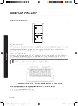
Return air requirements
Closet Wall
Typical Closet Installations
Provisions shall be made to permit the air in the rooms and the living spaces to return to the air handler. Failure to comply
may cause a reduction in the amount of return air available to the blower, causing reduced air flow resulting in improper
heating and cooling of the living space. The reduced air may cause the air flow handler to cycle on the limit causing
premature heating element failure (if electric heat kits are installed).
Upflow Accessory Filter Box Kit
An accessory filter box kit can be used on the return air end of the air handler when configured in the upflow position. The
filter kit is placed over the return plenum in the floor and sealed to the plenum using sealant or caulking material and/or
tape. The air handler is placed on top of the return filter box and the return opening sealed to prevent leaks.
NOTE
Make sure the flow arrow on the air filter is pointing towards the coil.
ADJUSTMENT KNOB
FOR 1" OR 2" FILTER
ADJUSTMENT KNOB
FOR 1" OR 2" FILTER
Accessory Air Filter Box for 1” or 2” Air Filters. Filter Size Adjustment knob is on both sides.
FILTER BASE ASSEMBLY KIT MODEL NUMBERS - FIELD INSTALLED, PURCHASED SEPARATELY
VFB-1 – 16” X 20” X 2” Small Cabinet (9/12/18/24K )
VFB-2 – 20” X 20” X 2” Medium Cabinet (30/36K)
VFB-3 – 20” X 24” X 2” Large Cabinet (48/54/60/72K)
AM072TNZDCH_IM_DVM V-AHU_AA_EN_.indd 10
2020-02-14 오전 10:33:30
Summary of Contents for AM0 SERIES
Page 45: ...45 English Appendix Memo AM072TNZDCH_IM_DVM V AHU_AA_EN_ indd 45 2020 02 14 오전 10 33 41 ...
Page 46: ...AM072TNZDCH_IM_DVM V AHU_AA_EN_ indd 46 2020 02 14 오전 10 33 41 ...
Page 91: ...45 Français Annexe Note AM072TNZDCH_IM_DVM V AHU_AA_FR_ indd 45 2020 02 14 오전 10 35 49 ...
Page 92: ...AM072TNZDCH_IM_DVM V AHU_AA_FR_ indd 46 2020 02 14 오전 10 35 49 ...


