20
English
Instal
lation
WARNING
•
For personal safety be sure to turn the electrical power “OFF” at the main entrance (Home
Circuit Breaker Box) and at the unit control box circuit breakers before attempting any service or
maintenance operations. Homeowners should never attempt to perform any maintenance which
requires opening the air handler control box door.
•
This air handler is not equipped with a shield that covers the line voltage electrical supply wires and
the circuit breaker connections. Take precautions to prevent accidental electrical shock. Be sure to
turn the electrical power “OFF” at the main entrance (Home Circuit Breaker Box) and at the control box
circuit breakers before removing the front panel.
Power supply wiring
•
The unit internal wiring is complete except for the power supply and control wires.
•
The use of cable connectors on incoming power supply wires to relieve any strain on wiring is recommended.
•
Follow the steps below to connect the power supply wires.
•
Supply voltage is 208/240V, 1ø, 60 Hz.
•
If you are installing optional heat kits, refer to the heat kit installation instructions for line voltage connection
instructions
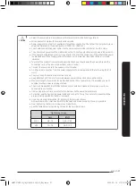
Single circuit line wiring connections
CAUTION
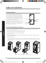
If an accessory heat kit is installed, power must enter the unit on the top or the top-left side of the unit as
shown below (A).
1. Before wiring work, you must turn off all power source.
2. Indoor unit power should be supplied through the breaker
(ELCB or MCCB+ELB ) separate from the outdoor power.
ELCB : Earth Leakage Circuit Breaker
MCCB : Molded Case Circuit Breaker
ELB : Earth Leakage Breaker
3. Only copper power cables should be used.
4. Remove the blower and control box access panel (door).
5. Install the cable connectors on the 7/8” diameter holes on the right
side of the control box.
6. Insert the wires through the holes in the casing and through the
cable connectors.
7. Connect the black supply wire to the L1[1(L)] high voltage connection
terminal with compressed ring terminals.
8. Connect the white supply wire to the L2[2(N)] high voltage
connection terminal with compressed ring terminals.
9. Connect the green wire to the ground lug near the supply wire
connections with a compressed ring terminal and tighten the ground
screw. Make sure to leave extra slack in the ground wire to allow
service to the unit without disconnecting the ground wire.
A
C
A
A
B
Left side
Right side
A - Power conduit connection opening
(must use when installing accessory electric heat kit).
B - Power conduit connection opening
(do not use when installing accessory electric heat kit).
C - Communication wire conduit connection opening
IMPORTANT - All insulation on field wiring must be rated at 140°F (60ºC) or higher. Please refer to the wiring diagrams on
the air handler or the tables in this manual for more information.
IMPORTANT - Refer to the NEC National Electrical Code (NFPA 70) or the Canadian Electrical Code, Part I (CSA C22.1) and
local codes for wiring material requirements.
Wiring Work
AM072TNZDCH_IM_DVM V-AHU_AA_EN_.indd 20
2020-02-14 오전 10:33:33
Summary of Contents for AM0 SERIES
Page 45: ...45 English Appendix Memo AM072TNZDCH_IM_DVM V AHU_AA_EN_ indd 45 2020 02 14 오전 10 33 41 ...
Page 46: ...AM072TNZDCH_IM_DVM V AHU_AA_EN_ indd 46 2020 02 14 오전 10 33 41 ...
Page 91: ...45 Français Annexe Note AM072TNZDCH_IM_DVM V AHU_AA_FR_ indd 45 2020 02 14 오전 10 35 49 ...
Page 92: ...AM072TNZDCH_IM_DVM V AHU_AA_FR_ indd 46 2020 02 14 오전 10 35 49 ...


