13
English
Instal
lation Pr
oc
edur
e
Step 8 Performing the gas leak test
To identify potential gas leaks on the indoor unit, inspect
the connection area of each refrigerant pipe using a leak
detector for R-410A.
Before recreating the vacuum and recirculating the
refrigerant gas, pressurize the whole system with
nitrogen (using a cylinder with a pressure reducer) at a
pressure above 4.1 MPa in order to immediately detect
leaks on the refrigerant fittings.
Made vacuum for 15 minutes and pressurizing system
with nitrogen.
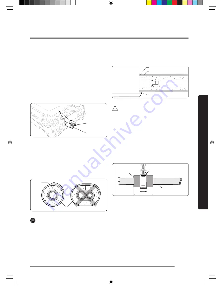
Liquid side
Gas side
Insulator
Step 9 Insulating the refrigerant pipes
Once you have checked that there are no leaks in the
system, you can insulate the piping and hose.
1
To avoid condensation problems, place Acrylonitrile
Butadien Rubber separately around each refrigerant
pipe.
No gap
NBR (T13.0 or thicker)
NOTE
•
Always make the seam of pipes face upwards.
2
Wind insulating tape around the pipes and drain hose
avoiding compressing the insulation too much.
3
Finish wrapping insulating tape around the rest of the
pipes leading to the outdoor unit.
4
The pipes and electrical cables connecting the indoor
unit with the outdoor unit must be fixed to the wall
with suitable ducts.
Insulation cover pipe
Insulation pipe
Be sure to overlap the insulation.
Indoor unit
CAUTION
•
Must fit tightly against body without any gap.
•
Install the insulation not to get wider and use the
adhesives on the connection part of it to prevent
moisture from entering.
•
Wind the refrigerant pipe with insulation tape if it is
exposed to outside sunlight.
•
Install the refrigerant pipe respecting that the
insulation does not get thinner on the bent part or
hanger of pipe.
•
Add the additional insulation if the insulation plate
gets thinner.
Refrigerant pipe insulation
Hanger
Additional
insulation
a
a x 3
•
Must fit tightly against body without any gap.
•
All refrigerant connection must be accessible, in order
to permit either unit maintenance or removal.
DVM TK Wind-Free 1way IM EN_DB68-07553A-00.indb 13
2017-12-01 오후 2:19:02


