background image

BEFORE InSTallaTIOn

Safety precautions

Keep this installation manual together with the user’s manual in a handy place so that you can find it whenever you need to 
see it after reading this manual thoroughly .

Make sure to read the following safety precautions carefully before installation .

Make sure to observe the cautions specified in this manual .

Conduct a test run of the unit after installation and then explain all system functions to the owner .

The indications and meanings are as shown below .
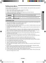
 WARNING

Hazards or unsafe practices that may result in 

severe personal injury or death.

 CAUTION

Hazards or unsafe practices that may result in 

minor personal injury (to installer/user) or 

property damage.

SEVERE WARNING SIGNS

f

f

Do not install the unit by yourself . Incorrect installation of the unit could cause injury due to fire, electric shock and water 
leakage or from the unit falling . Consult a dealer or a qualified installer .

f

f

Place a grille over the air inlet to prevent birds nesting inside .

f

f

Do not attempt to repair, move, modify or reinstall the unit on your own . Make sure that these installations are carried out 
by qualified personnel to avoid electric shock or fire .

f

f

Check if the voltage and the frequency of the main power supply are required for the unit to be installed and check the 
connection .

f

f

The electric work must be done by service agent or similarly qualified person according to national wiring regulations 
and use only rated cable . If the capacity of the electric work is not properly completed, electric shock or fire may occur .

f

f

Make sure the air intake is located far from an exhaust port of a burner . It may cause oxygen shortage .

f

f

Ground the unit . Do not connect the ground to a gas pipe, water pipe, lighting rod or telephone grounding . Defective 
grounding could cause electric shock .

f

f

Do not leave electrical connections loose, to do so may cause sparking, heat build up or electrical shock .

f

f

Install separate MCCB and ElB when installing the power cable . If you do not install the MCCB and ElB, electric shock or 
fire may occur .

f

f

If the power plug is damaged, replace it by the manufacturer or qualified personnel to avoid the risk .

f

f

Disconnect the circuit breaker when you don’t use the product for a long period of time to save energy . 

f

f

Do not install the electrical cables under tension; doing so may lead to electrical disconnection and attendant problems .

f

f

Disconnect the electrical supply before carrying out repairs .

f

f

Do not pull the electric wire or touch the power plug with wet hands .

f

f

Installers are required to read the general information carefully for safety .

f

f

Do not put the product near dangerous substances to prevent fire, explosion or injury and do not expose the product to 
direct sunlight .

f

f

avoid the use of an extension cord and do not share the power outlet with other appliances . Incomplete connection, 
defective insulation or exceeding the permissible current may cause electric shock or fire .

f

f

Make sure to turn off the main power when setting up the product’s electric circuit or power cords . There is electric shock .

f

f

The product should be installed in accordance with the national Electrical regulations .

f

f

Ensure that the national safety code requirements have been followed for the main supply circuit . Ensure that a properly 
sized and connected ground wire is in place .

ENGLISH-3

01


BE

fo

RE

 INS

tALL
At

Io

N

ERV_IM_EN_DB68-05252A-02.indd   3

2016-05-27   오전 11:26:39

Summary of Contents for AN026JSKLKN Series

Page 1: ...es AN080JSKLKN Series AN100JSKLKN Series ERV Energy Recovery Ventilator installation manual imagine the possibilities Thank you for purchasing this Samsung product DB68 05252A 02 EN ES FR IT PT NL DE ERV_IM_EN_DB68 05252A 02 indd 45 2016 05 27 오전 11 26 56 ...

Page 2: ...n 9 Installingtheproduct Hanging the ERV 11 Electric wiring 12 Schematic diagram 17 Connecting the unit 18 Installing the duct 27 Others Performance graph 29 Final Checks andTrial Operation 31 Setting address of the ERV and installation option 32 ENGLISH 2 ERV_IM_EN_DB68 05252A 02 indd 2 2016 05 27 오전 11 26 39 ...

Page 3: ...t of a burner It may cause oxygen shortage f f Ground the unit Do not connect the ground to a gas pipe water pipe lighting rod or telephone grounding Defective grounding could cause electric shock f f Do not leave electrical connections loose to do so may cause sparking heat build up or electrical shock f f Install separate MCCB and ELB when installing the power cable If you do not install the MCC...

Page 4: ...ckaging material used for your new appliance are compatible with the environment and can be recycled f f Dispose of the packaging material in accordance with the local requirements f f Install a ground leakage breaker depending on the installation place where it is humid If not it may cause electric shock f f The product must be installed according to the national electrical regulations f f The ma...

Page 5: ...Inspection hole for filter heat exchange element fan motor and damper Return Air 600 mm The ERV should be installed in a ceiling which has enough space above as seen in the picture 20 mm 370 mm NOTE ENGLISH 5 01 Before Installation ERV_IM_EN_DB68 05252A 02 indd 5 2016 05 27 오전 11 26 39 ...

Page 6: ...exchange element fan motor and damper Return Air A B Unit mm Model A B Number of heat exchange elements 035 050 1000 600 2 080 100 1135 800 The ERV should be installed in a ceiling which has enough space above as seen in the picture 20 mm C Unit mm Model C 035 050 300 080 100 370 NOTE ENGLISH 6 ERV_IM_EN_DB68 05252A 02 indd 6 2016 05 27 오전 11 26 39 ...

Page 7: ...n Air Air discharging hole Air exhaust grille Supply Air duct 035 050 080 100 Supply Air Exhaust Air duct Hood Anchor bolt Insulation Outdoor Air suction duct Hood Outdoor Air Return Air duct Air intake hole Air exhaust grille Return Air Air discharging hole Air exhaust grille Supply Air duct 3 m ENGLISH 7 01 Before Installation ERV_IM_EN_DB68 05252A 02 indd 7 2016 05 27 오전 11 26 39 ...

Page 8: ...tact the user directly because in winter time the cold supplied air may give an unpleasant feeling when it reaches the user Noise may increase when there are large amount of exhausting air Be sure to install the duct based on standard air volume When necessary control the air volume by installing volume damper If the noise continues install an additional noise attenuator Volume damper noise chambe...

Page 9: ...e cover 1 Heat exchange element 1 Dust filter 2 Hanger 4 Electrical component box 1 Unit mm Model A B C E F G H I J K M N P Q R 026 600 660 70 510 675 729 102 470 85 98 242 ø 140 ø 156 133 350 Ensure the space for installing and repairing NOTE ENGLISH 9 01 Before Installation ERV_IM_EN_DB68 05252A 02 indd 9 2016 05 27 오전 11 26 40 ...

Page 10: ... 1 Heat exchange element 2 Dust filter 4 Hanger 4 Electrical component box 1 Unit mm Model A B C E F G H I J K M N P 035 050 1000 1012 99 940 6 1036 4 26 130 617 253 135 270 Ø 194 Ø 241 5 080 100 1135 1220 84 1110 1183 25 184 613 3 387 8 170 340 Ø 244 Ø 270 Ensure the space for installing and repairing NOTE ENGLISH 10 ERV_IM_EN_DB68 05252A 02 indd 10 2016 05 27 오전 11 26 40 ...

Page 11: ...ng space for hanging the unit 4 Hang the unit horizontally to the suspension bolts between two nuts 5 Fasten the nuts to suspend the unit The washer should be fit for the hanger Suspension bolt ø 10 ø 12 Nut Washer Hanger Washer Nut Rubber Rubber Lock nut Ensure that the ceiling is strong enough to support the weight of the unit Before hanging the unit test the strength of each attached suspension...

Page 12: ...35 050 080 100 Electrical component box Use a cable tie here to retain the cable Maintenance cover Hanger Hanger Use a cable tie here to retain the cable Maintenance cover Electrical component box Inside Wiring outlet Location for option interface PCB Main PCB Grounding ENGLISH 12 ERV_IM_EN_DB68 05252A 02 indd 12 2016 05 27 오전 11 26 41 ...

Page 13: ... Connect the cable to the terminal board with a compressed ring terminal Fix the screws in the electrical component box with designated torque referring to the table Recommended size Tightening torque kgf cm Power Cable M4 12 0 18 0 Communication Cable M3 5 8 0 12 0 1 N m 10 kgf cm Do not wash the heat exchange element It may decrease the efficiency The unit should be installed in accordance with ...

Page 14: ...nication connection part F1 F2 Communication between ventilation systems communicate with interface module V1 V2 Power supply connector for interface module F3 F4 Wired remote controller communication TB_COMM BLK Thermal Fuse status input connector Inputs status ofThermal Fuse within the power terminal block CN140 WHT Internal damper power supply Damper motor control part for switching ventilation...

Page 15: ...UTION Unit mm 120 60 20 20 20 180 Power cable 3 Insert both sides of core wire of the power cable into the connection sleeve f f Method 1 Push the core wire into the sleeve from both sides Connection sleeve f f Method 2 Twist the wire cores together and push it into the sleeve Connection sleeve 4 Using a crimping tool compress the two points and flip it over and compress another two points in the ...

Page 16: ...ed wrap it with the insulation tape to finish Make sure that the connection parts are not exposed to outside Be sure to use insulation tape and a contraction tube made of approved reinforced insulating materials that have the same level of withstand voltage with the power cable Comply with the local regulations on extensions CAUTION Insulation tape In case of extending the electric wire please DO ...

Page 17: ...er and communication cables are not supplied with ERV unit Power supply cords of parts of appliances for outdoor use shall not be lighter than polychloroprene sheathed flexible cord Code designation IEC 60245 IEC 57 CENELEC H05RN F or IEC 60245 IEC 66 CENELEC H07RN F CAUTION ENGLISH 17 02 Installing the product ERV_IM_EN_DB68 05252A 02 indd 17 2016 05 27 오전 11 26 43 ...

Page 18: ...erface module to theV1 V2 terminal of the ERV PCB DC 12V 2 Connect the CN3 of the ERV interface module to the F1 F2 terminal of the ERV PCB Check the polarity when connecting CN4 of the interface module and theV1 V2 of the ERV Connection ofV1 andV2 must not be switched CAUTION ERVWired Remote controller Electric wire Field supplied ERVWired Remote controller ERV PCB 1 Remove the back cover of the ...

Page 19: ...roller at once CAUTION Setting the OnOff controller CN4 CN3 RED CN2 BLK ERV interface module MIM N10 F1 F2 OnOff Controller Maximum 16 ERV units can be connected to 1 ERV interface module Maximum 128 units ex ERV duct indoor unit etc can be connected to 1 OnOff controller MAIN address Required address for communication between ventilation systems If the MAIN address is not set address will be set ...

Page 20: ...D CN2 BLK CN4 CN3 RED CN2 BLK ERV MAIN 0 RMC 0 ERV interface module 0 OnOff controller ERV interface module 1 ERV MAIN 1 RMC 1 ERV MAIN 2 RMC 2 ERV MAIN 3 RMC 3 ERV MAIN 4 RMC 4 ERV MAIN 0 RMC 5 ERV MAIN 1 RMC 6 ERV MAIN 2 RMC 7 ERV MAIN 3 RMC 8 ERV MAIN 4 RMC 9 If you turn on the switch No 00 of the OnOff controller ERV with RMC address 0 will be turned on and starts to operate NOTE ENGLISH 20 ER...

Page 21: ...MAIN 0 RMC 0 ERV interface module 0 OnOff controller ERV interface module 1 ERV MAIN 1 RMC 0 ERV MAIN 2 RMC 0 ERV MAIN 3 RMC 0 ERV MAIN F RMC 0 ERV MAIN 0 RMC F ERV MAIN 1 RMC F ERV MAIN 2 RMC F ERV MAIN 3 RMC F ERV MAIN F RMC F If you turn on the switch No 00 of the OnOff controller ERV with RMC address 0 will be turned on and starts to operate You can control up to 128 units Power on off NOTE EN...

Page 22: ...ntroller can be controlled via F3 F4 CN4 CN3 RED CN2 BLK F1 F2 ERV interface module OnOff controller F3 F4 ERV wired remote controller ERV MAIN 0 RMC 2 ERV MAIN 1 RMC 0 ERV MAIN 2 RMC 0 ERV MAIN 3 RMC 0 ERV MAIN F RMC 0 ERV wired remote controller communicates by automatic addressing method which doesn t require address setting NOTE ENGLISH 22 ERV_IM_EN_DB68 05252A 02 indd 22 2016 05 27 오전 11 26 4...

Page 23: ...or over Bar Nut Washer Hanger Washer Nut Rubber Rubber Lock nut Install the product at a place it can withstand the weight of the product Attach an insulator T10 between the products to prevent vibration and condensation Install bars under the product to bear the weight of the product and use anchor bolts that are Φ 12 or larger Bar insulator anchor bolt and nut should be purchased separately CAUT...

Page 24: ...al controller 1 is set to ON position ERV is operated in the last used condition f f Using Kitchen hood It connects both sides of HOOD If you enter a kitchen hood the supply air operates inTurbo fan speed and exhaust air operates in Low fan speed HOOD EXT1 External control 1 Kitchen hood DRY CONTACT DRY CONTACT Connecting external load f f Connection is necessary to use humidifying unit or damper ...

Page 25: ... KEY 2 various data will be displayed f f Displayed data will vary as shown in below table depending on the number of times you press the KEY 2 Number of pressed times Displayed content Example Display on segment SEG1 SEG2 SEG3 SEG4 1 Discharge air fan RPM 1 350 RPM 1 1 3 5 2 Supply air fan RPM 950 RPM 2 Off 9 5 3 Indoor temperature 25 C 3 Off 2 5 4 Outdoor temperature 30 C 4 Off 3 0 5 CO2 concent...

Page 26: ...between ERV wired remote controller ERV When there s communication interruption for 3 minutes after detecting the ERV Others EEPROM error OPTION setting error Option not inputted Error on thermal fuse within the power terminal block Open Operation is stopped because outdoor indoor temperature is below 0 degree celsius Damper error Error will be detected when there s no input from the switch for 10...

Page 27: ...or ducts should be securely insulated Refer to below illustration f f Duct and external hood installation must comply local ventilation equipment installation standards f f Duct on the outdoor side should be at least 3 m long from the product to prevent rain water from entering to the product via duct f f Motorized damper and Back draft damper should be installed according to damper installation s...

Page 28: ...t damper Motorized damper Commercial ERV Conditionally mandatory Refer to the table below Conditionally mandatory Refer to the table below Recommended Recommended Environmental condition Installation condition Motorized damper back draft prevention damper installation requirement Waterfront Within 1 000 m Required Mandatory Lake rivers Within 500 m Required Mandatory Buildings Underground installa...

Page 29: ...00 150 200 250 300 350 400 450 0 Fan characteristics External static pressure Pa Air volume CMH Turbo High Low Efficiency Efficiency Air volume CMH Temperature Cooling Enthalpy Heating Enthalpy 050 0 0 100 200 300 400 500 600 700 800 900 1000 100 50 150 200 250 300 10 0 20 30 40 50 60 70 80 90 100 0 50 100 150 200 250 300 350 400 450 500 550 600 650 Fan characteristics External static pressure Pa ...

Page 30: ...me CMH Temperature Cooling Enthalpy Heating Enthalpy 100 0 100 200 300 400 500 600 700 800 900 1000 1100 1200 1300 1400 1500 0 400 350 300 250 200 150 100 50 0 10 0 20 30 40 50 60 70 80 90 100 50 0 100 150 200 250 300 350 400 450 500 550 600 650 700 750 800 850 900 1000 1050 1100 1200 1150 950 0 Fan characteristics External static pressure Pa Air volume CMH Turbo High Low Efficiency Efficiency Air...

Page 31: ...d air outlet is controlled byTurbo High Low Located on the corner Open By Pass mode Turbo High Low Located on side Closed f f If an error occurs during trial operation check out the wiring Turn off the sub power supply and carry out the wiring work again f f After the trial operation explain how to use the ERV to the user and hand over the product with the user s manual Temperature range for using...

Page 32: ... remote controller 2 While pressing and holding the Temp and Temp buttons insert the batteries 3 Check whether you enter the option setting stage Step 2 Procedure of option setting After entering the option setting stage select the option as shown below 24 digits are available to be input for the option setting SEG1 SEG7 SEG13 and SEG19 are page option so they do not need to be set Set the each 2 ...

Page 33: ... Fan mode Press Mode button to select Fan mode in On status 7 Setting SEG9 SEG10 option Press Fan button to enter SEG9 value Press Fan button to enter SEG10 value Each time you press the button will be selected in rotation SEG9 SEG10 8 Setting Heat mode Press Mode button to select Heat mode in On status 9 Setting SEG11 SEG12 option Press Fan button to enter SEG11 value Press Fan button to enter SE...

Page 34: ...ion SEG21 SEG22 18 Setting Heat mode Press Mode button to select HEAT mode in Off status 19 Setting SEG23 SEG24 mode Press Fan button to enter SEG23 value Press Fan button to enter SEG24 value Each time you press the button will be selected in rotation SEG23 SEG24 Step 3 Check the option you have set After setting option press Mode button to check whether the option code you input is correct or no...

Page 35: ...No 0AXXXX 1XXXXX 2XXXXX 3XXXXX Option SEG1 SEG2 SEG3 SEG4 SEG5 SEG6 Description Page Mode Setting main address No function 10 digit of ERV The unit digit of an ERV Indication and Details Indication Details Indication Details Indication Details Indication Details Indication Details 0 A 0 No main address 0 4 10 digit 0 9 Unit digit 1 Address setting mode Option SEG7 SEG8 SEG9 SEG10 SEG11 SEG12 Descr...

Page 36: ...o function Indication and Details Indication Details Indication Details Indication Details 0 2 0 Disable 1 Enable Option SEG7 SEG8 SEG9 SEG10 SEG11 SEG12 Description Page No function No function No function No function No function Indication and Details Indication Details 1 Option SEG13 SEG14 SEG15 SEG16 SEG17 SEG18 Description Page No function No function Use ofVirus Doctor No function Filter usa...

Page 37: ...age Use of humidity sensor Temperature setting of fresh cooling in auto mode operation CO2 level setting Air volume switch control No function No function Indication and Details Indication Details Indication Details Indication Details Indication Details 3 0 Disable 0 Disable 0 900 1 Enable 1 18 C 1 950 2 19 C 2 1000 3 20 C 3 1050 4 21 C 4 1100 5 22 C 5 1150 6 23 C 6 1200 7 24 C 8 25 C 9 26 C ENGLI...

Page 38: ...ng the buttons select a main menu number and press the Away button to enter the sub menu setting screen Using the buttons select a sub menu number and press the Away button to enter data setting screen When you enter the setting stage the current setting will be displayed Refer to the chart for data settings Using the buttons select the settings Press the Away button to move to the next setting Pr...

Page 39: ...of target 1 Group address 00H FEH hexadecimal 3 4 Setting checking product option Basic option of target 10 1 Option code of indoor units or ERV units 5 Setting Checking installation option 1 Installation option of target 10 1 Refer to the installation manual of connected indoor units or ERV units 6 Setting Checking installation option 2 Installation 2 option of target 10 1 Refer to the installati...

Page 40: ...13 SEG14 SEG15 SEG16 SEG17 SEG18 SEG19 SEG20 SEG21 SEG22 SEG23 SEG24 2 X X X X X 3 X X X X X The current SEG displayed can be distinguished by operation mode On and Off icon SEG2 SEG6 SEG8 SEG12 On Heat EX By Pass Auto Quiet Away SEG14 SEG18 SEG20 24 Off Heat EX By Pass Auto Quiet Away SEG 2 3 PAGE 1 PAGE 6 PAGE 2 PAGE 7 PAGE 3 PAGE 8 PAGE 4 PAGE 9 PAGE 5 PAGE 10 SEG 14 15 SEG 4 5 SEG 16 17 SEG 6 ...

Page 41: ...s 0 D 5 1 5 1 Example To set Centralized control to use among installation option Default Enable Option SEG1 SEG2 SEG3 SEG4 SEG5 SEG6 Description Page Mode The option mode you want to change Tens digit of option SEG to change Unit digit of option SEG to change Changed value Settings 0 D 2 0 5 0 Example To set Filter usage hours to 2000 Hour among installation option Option SEG1 SEG2 SEG3 SEG4 SEG5...

Page 42: ...Memo ENGLISH 42 ERV_IM_EN_DB68 05252A 02 indd 42 2016 05 27 오전 11 26 56 ...

Page 43: ...ENGLISH 43 03 Others ERV_IM_EN_DB68 05252A 02 indd 43 2016 05 27 오전 11 26 56 ...

Page 44: ...ERV_IM_EN_DB68 05252A 02 indd 44 2016 05 27 오전 11 26 56 ...

Reviews: