Samsung Electronics
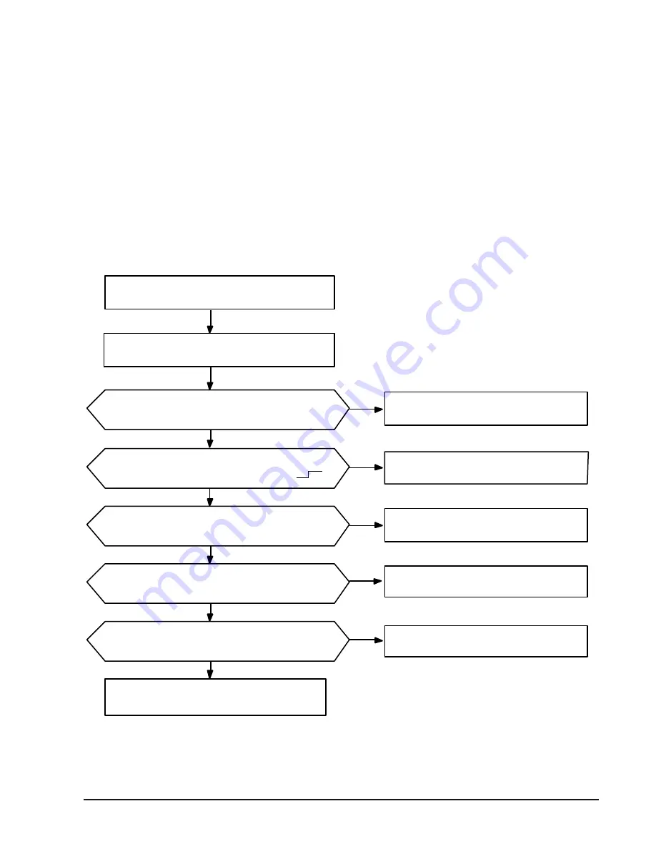
5-3-3 When the left and right adjusting plate Does not Operate
1) Trouble cause
Disconnection, wrong connection or bad contact of connected wire to the left and right adjusting motor.
Left and right adjusting motor defect.
Main PCB defect(RY83,IC03, MICOM)
2) Check items
Is the wire connecting the main PCB to the left and right adjusting motor good?
3) Sequence of check
Troubleshooting
Select the right and left swing mode by remocon
after opration on.
Tu rn off the power, and then turn it on in 5 seconds
Does the right and left adjusting plate work corre c t l y ?
Left and right adjusting motor
under normal operation.
Check MICOM(IC01) and replace it.
Check the wire connection error or disconnection,
bad contact.
Check the wire disconnection or bad contact.
N
Y
Y
Y
Y
N
N
N
N
Y
Check IC03 and replace it.
Check the left and right adjusting motor and replace it.
Is the voltage across the relay (RY83)DC 12V?
(Check after swing to the left and right.)
Is the voltage across the main PCB of CN78AC 220V?
(Check after swing to the left and right.)
Is the voltage across the left and right adjusting motor AC 220V?
(Check after swing to the left and right.)
It is high when checking the output wave of the pin no. 13 of
MICOM(IC01)? (Check after swing to the left and right.)
5-5
Summary of Contents for APH180HD
Page 4: ...2 2 Samsung Electronics 2 2 Dimensions Indoor Unit Outdoor Unit unit mm 330...
Page 31: ...Samsung Electronics 6 7 6 2 Outdoor unit...
Page 38: ...Samsung Electronics 8 1 8 PCB Diagrams 8 1 Ass y Main PCB...
Page 42: ...Samsung Electronics 8 5 8 2 Ass y PANEL PCB...
Page 45: ...Samsung Electronics 9 1 9 Wiring Diagrams 9 1 Indoor Unit 9 1 1...
Page 46: ...Samsung Electronics 9 2 9 1 2 Wiring Diagrams...
Page 47: ...Samsung Electronics 9 3 Wiring Diagrams 9 1 3...
Page 49: ...10 1 10 Schematic Diagrams 10 1 Indoor Unit Samsung Electronics...
Page 50: ...Samsung Electronics 10 2 10 2...
Page 51: ...Samsung Electronics 10 3 10 3...


