background image

Alignment and Adjustments

Samsung Electronics

3-6

7

8

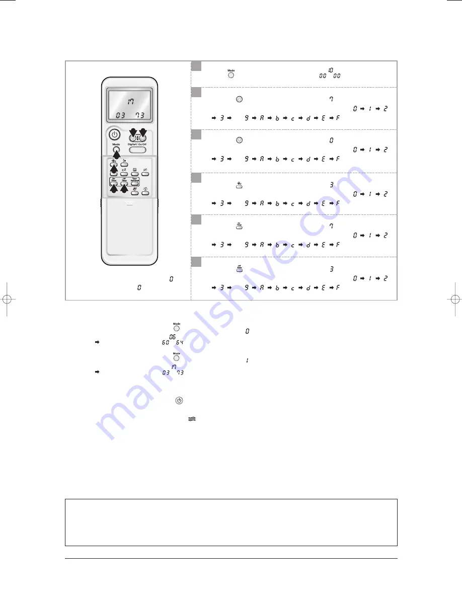
Press       button, then the default value is                .

Push the       button to set the display panel to 

.

Every time you push the button, the display panel reads 

. . .

repeatedly.

10

Push the       button to set the display panel to 

.

Every time you push the button, the display panel reads 

. . .

repeatedly.

9

Push the       button to set the display panel to 

.

Every time you push the button, the display panel reads 

. . .

repeatedly.

11

Push the       button to set the display panel to 

.

Every time you push the button, the display panel reads 

. . .

repeatedly.

12

Push the       button to set the display panel to 

.

Every time you push the button, the display panel reads 

. . .

repeatedly.

9

8

7

10

11

12

Setting is not required if you must 

a value which has a 

default.

Step 3 : Upon completion of the selection, check you made right selections.

Press the Mode Selection key,       to set the display part to 

and check the display part.

The display part shows               .

Press the Mode Selection key,       to set the display part to 

and check the display part.

The display part shows               .

Step 4 : Pressing the ON/OFF button (

)

When pressing the operation ON/OFF key with the direction of remote control for unit, the sound ''Ding'' or ''Diriring'' 

is heard and the OPERATION ICON(

) lamp of the display is flickering at the same time, then the input of option is

completed. (If the diriring sound isn't heard, try again pressing the ON/OFF button.)

Step 5 : Unit operation test-run

First,

Remove the battery from the remote control.

Second,

Re-insert the battery into the remote control.

Third,

Press ON/OFF key with the direction of remote control for set.

• Error Mode

1

st

If all lamps of indoor unit are flickering, plug out, plug in power plug again and press the ON/OFF key to retry.

2

nd

If the unit is not working properly or all lamps are continuously flickering after setting the option code, see if the correct option code

is set up for its model.

 24610A(1)_1  11/10/05 6:26 PM  Page 3-6

Summary of Contents for AS12HPCN

Page 1: ...eaning System The anti allergy filter and activated deodorizing filter are adopted Human Touch Remote control SERVICE Manual For more information Please access to our service web site http itself sec...

Page 2: ...cations of Product 2 5 2 5 Accessory and Option Specifications 2 7 13 Alignment and Adjustments 3 1 3 1 Error mode and check method 3 1 3 2 Setting Option Setup Method 3 5 14 Disassembly and Reassembl...

Page 3: ...2 2 Fault Diagnosis by Symptom 12 2 12 3 PCB Inspection Method 12 6 12 4 Main Part Inspection Method 12 8 13 Block Diagram 13 1 14 Reference Sheet 14 1 14 1 Index for Model Name 14 1 14 2 Refrigerant...

Page 4: ...n order to avoid a hazard The air conditioner must be plugged into an independent circuit if applicable or connect the power cable to the auxiliary circuit breaker An all pole disconnection from the p...

Page 5: ...safety Current is measured according to ISO standard for energy efficiency 1 4 Disposing of the unit Before throwing out the air conditioner remove the batteries from the remote control When you dispo...

Page 6: ...ow this product to set place in anywhere Excellent dust collection filter With a metallic dust filter that upgrades the dust collection function than a common plastic filter you can enjoy the best cle...

Page 7: ...ndicator Blue Remote control sensor Room Temperature sensor Air Inlet Note In the Auto mode 2 fan indicators increase and decrease continuously and turn round In the modes except the Auto mode the fan...

Page 8: ...Product Specifications 2 3 Samsung Electronics 2 2 2 Outdoor Unit Air Inlet Rear Air Outlet Connection Valve...

Page 9: ...ondition Indoor unit Outdoor unit Wall mounted 2 70 2 90 1 0 7 5 6 9 6 3 25 8 0 7 4 6 8 25 40 30 51 40 30 51 3 21 3 41 1 220 240 50 840 850 3 7 3 7 97 3 97 3 21 2 1 5G 250V 10A 950x268x165 720x530x260...

Page 10: ...ay Rotation Blue LED Display Net Weight Indoor Unit Outdoor Unit Outer Dimension Indoor Unit Outdoor Unit Noise Indoor Unit Outdoor Unit Air Purifying System Filter Indoor Display Item Indoor Unit Out...

Page 11: ...Blue LED Display Net Weight Indoor Unit Outdoor Unit Outer Dimension Indoor Unit Outdoor Unit Noise Indoor Unit Outdoor Unit Air Purifying System Filter Indoor Display Item Indoor Unit Outdoor Unit A...

Page 12: ...S INSTRUCTIONS MANUAL DE INSTRUCCIONES ISTRUZIONI PER L USO MANUAL DE INSTRU ES MANUEL D UTILISATION GEBRAUCHSANWEISUNG Splut type Room Air Conditioner Aire acondicionado dom stico sistema Split Condi...

Page 13: ...2mm 09 DB96 04578G 1 Vinyl Tape Width 50mm DB72 00459A 1 Drain Plug DB67 20011A 1 Rubber Leg DB73 00179A 4 Pipe Clamps A DB39 20224A 3 Pipe Clamps B DB39 20224B 3 Cement Nail 6 M4x16 Tapping Screws 60...

Page 14: ...ethod Error Mode LAMP 7 segment Display Indoor unit room temperature sensor error open or short Indoor unit heat exchanger temperature sensor error open or short Indoor fan motor malfunction EEPROM er...

Page 15: ...nsor from the ASS Y PCB CN43 connector and measure the sensor resistance with an ohmmeter tester between Pin 1 and 2 Connect the sensor to CN43 supply power and measure the voltage of 1 and 2 of the C...

Page 16: ...t replace the room pipe sensor 3 Assemble the room pipe sensor to PCB plug in and check the voltage of connector 3 and 4 If the resistance is below 0 5V or over 4 9V replace the indoor Main PCB short...

Page 17: ...ted within 5 seconds Does the OPERATION lamp blink Does the Solid State Relay SS71 work properly Is the supply voltage of the fan motor sufficient Test rod location PCB CN72 Condition About AC180V Nor...

Page 18: ...the display panel reads or repeatedly Setting is not required if you must a value which has a default Push the button to set the display panel to Every time you push the button the display panel read...

Page 19: ...ction key to set the display part to and check the display part The display part shows Press the Mode Selection key to set the display part to and check the display part The display part shows Step 4...

Page 20: ...ung Electronics OPTION ITEMS REMOCON MODEL SEG1 SEG2 SEG3 SEG4 SEG5 SEG6 SEG7 SEG8 SEG9 SEG10 SEG11 SEG12 AS09HPC AS09HPD 0 2 7 0 2 4 1 7 1 2 1 8 0 2 7 0 2 4 1 7 0 2 1 8 AS12HPC 0 2 7 0 2 6 1 7 1 2 6...

Page 21: ...ing the unit No Parts Procedure Remark 1 Panel Front 1 Stop the air conditioner operation and shut off the main power 2 Detach the Front Grille after pushing out it 3 Loosen 1 of the right screw and d...

Page 22: ...in Heat Exchanger 6 Loosen 5 fixing screws of Panel Front 7 Unlock 2 hooks to fix Panel Front and Tray Drain 8 Unlock 2 hooks to fix Panel Front and Back Body 1 Detach the connected wire of Stepping M...

Page 23: ...3 No Parts Procedure Remark 2 Detach the Room Sensor 3 Detach the Holder Pipe at the rear side of the unit 4 Loosen 3 fixing screws of left Holder Evap 5 Loosen 1 fixing screw of right Holder Motor 6...

Page 24: ...right Holder control 2 Take all the connector of PCB upper side out Including Power Cord 3 Detach the outdoor unit connection wire from the Terminal Block 4 Pull the PCB up to detach 1 Loosen 2 fixing...

Page 25: ...ark 1 Common Work 1 Unplug the electric power before disassembling 2 Loosen the fixing screws of the Cover Control 3 Loosen the fixing screws of the Plate Control 4 Loosen the fixing screws of the Cab...

Page 26: ...No Parts Procedure Remark 2 Fan Motor 6 Loosen the fixing screws of the Cabinet Front 1 Remove the Nut Flange Turn to the clockwise 2 Detach the Fan 3 Loosen 4 fixing screws to detach the Motor 4 Dis...

Page 27: ...Loosen 2 fixing screws on both sides 2 Disassemble the pipe in both inlet and outlet with welding torch 3 Detach the Heat Exchanger 1 Loosen the Nut to open the Terminal Cover 2 Disassemble the Cloth...

Page 28: ...MEMO 4 8 Samsung Electronics...

Page 29: ...1 10 12 16 11 13 19 21 22 15 7 23 23 1 3 6 17 14 1 18 9 4 8 5 14 6 14 1 1 1 1 3 9 2 9 3 2 5 23 2 3 2 3 4 3 1 3 3 2 1 2 6 2 5 1 2 4 2 2 2 3 9 1 1 2 14 5 14 2 14 3 14 4 20 2 5 Exploded Views and Parts...

Page 30: ...SGCC M 1 1 6 DB61 02050A HOLDER EVAP ABS 1 1 7 DB61 02052A HOLDER MOTOR PP 1 1 8 DB93 02804B ASS Y CONTROL IN ASS Y 1 1 9 DB96 04464C ASS Y EVAP TOTAL ASS Y 1 DB96 03835A ASS Y EVAP TOTAL ASS Y 1 9 1...

Page 31: ...0 00515A PLATE CONTACT SUS 304 1 1 19 DB70 00516A PLATE CONTROL IN SGCC M 1 1 20 DB93 01549B ASS Y CONNECTOR POWER ASS Y 1 1 21 DB93 03016R ASS Y REMOCON ARH 1315 1 1 22 DB92 00643F ASS Y GRILLE ASS Y...

Page 32: ...OL SGCC M 1 1 6 DB61 02050A HOLDER EVAP ABS 1 1 7 DB61 02052A HOLDER MOTOR PP 1 1 8 DB93 02804A ASS Y CONTROL IN ASS Y 1 1 9 DB96 04464C ASS Y EVAP TOTAL ASS Y 1 DB96 03835A ASS Y EVAP TOTAL ASS Y 1 9...

Page 33: ...0 00515A PLATE CONTACT SUS 304 1 1 19 DB70 00516A PLATE CONTROL IN SGCC M 1 1 20 DB93 01549B ASS Y CONNECTOR POWER ASS Y 1 1 21 DB93 03016R ASS Y REMOCON ARH 1315 1 1 22 DB92 00643F ASS Y GRILLE ASS Y...

Page 34: ...MEMO 5 6 Samsung Electronics...

Page 35: ...Samsung Electronics 5 7 12 15 1 15 2 24 14 5 15 5 18 19 9 2 11 22 10 21 15 4 20 4 7 6 23 8 3 1 16 17 15 3 15 13 5 2 Outdoor Unit...

Page 36: ...0520D ASS Y PARTITION ASS Y 1 1 SA 15 DB93 03843B ASS Y CONTROL OUT ASS Y 1 SA DB93 03843A ASS Y CONTROL OUT ASS Y 1 SA 15 1 2501 001238 CAPACITOR COMP 40uF 450VAC 1 SA 2501 001239 CAPACITOR COMP 45uF...

Page 37: ...DB70 00516A PLATE TERMINAL LOW SGCC M T1 2 1 SNA 6 DB61 00171A HOLDER WIRE CLAMP ABS 1 SA 7 6001 000929 SCREW MACHINE PH M3xL22 1 SNA 8 6001 001054 SCREW MACHINE TH M4xL10 2 SNA 9 DB93 02827A C W MAI...

Page 38: ...09A ASS Y MELODY PCB ASS Y 1 SA 5 DB70 00516A PLATE TERMINAL LOW SGCC M T1 2 1 SNA 6 DB61 00171A HOLDER WIRE CLAMP ABS 1 SA 7 6001 000929 SCREW MACHINE PH M3xL22 1 SNA 8 6001 001054 SCREW MACHINE TH M...

Page 39: ...0 50V Y5V TP 2012 1 SNA C403 2203 000192 C CER CHIP 100nF 80 20 50V Y5V TP 2012 1 SNA C404 2203 001562 C CER CHIP 10nF 80 20 50V Y5V TP 2012 1 SNA C405 2203 000444 C CER CHIP 1nF 10 50V X7R 2012 1 SNA...

Page 40: ...01 000534 TR SMALL SIGNAL 2SC2412K NPN 200mW SOT 23 TP 1 1 SNA Q602 0501 002296 TR SMALL SIGNAL MMST2907A PNP 200mW SMT3 TP 100 3 1 SNA Q603 0501 000534 TR SMALL SIGNAL 2SC2412K NPN 200mW SOT 23 TP 1...

Page 41: ...31 R CHIP 470ohm 5 1 8W TP 2012 1 SNA R609 2007 000030 R CHIP 560ohm 5 1 8W TP 2012 1 SNA R610 2007 000468 R CHIP 1Kohm 5 1 8W TP 2012 1 SNA R611 2007 000468 R CHIP 1Kohm 5 1 8W TP 2012 1 SNA R908 200...

Page 42: ...2012 1 SNA C403 2203 000192 C CER CHIP 100nF 80 20 50V Y5V TP 2012 1 SNA C404 2203 001562 C CER CHIP 10nF 80 20 50V Y5V TP 2012 1 SNA C405 2203 000444 C CER CHIP 1nF 10 50V X7R 2012 1 SNA C501 2203 0...

Page 43: ...IGNAL 2SC2412K NPN 200mW SOT 23 TP 1 1 SNA Q601 0501 000534 TR SMALL SIGNAL 2SC2412K NPN 200mW SOT 23 TP 1 1 SNA Q602 0501 002296 TR SMALL SIGNAL MMST2907A PNP 200mW SMT3 TP 100 3 1 SNA Q603 0501 0005...

Page 44: ...2012 1 SNA R608 2007 000931 R CHIP 470ohm 5 1 8W TP 2012 1 SNA R609 2007 000030 R CHIP 560ohm 5 1 8W TP 2012 1 SNA R610 2007 000468 R CHIP 1Kohm 5 1 8W TP 2012 1 SNA R611 2007 000468 R CHIP 1Kohm 5 1...

Page 45: ...ONNECTOR HEADER BOX 6P 1R 2mm ANGLE SN 1 SNA CN86 3711 004386 CONNECTOR HEADER BOX 3P 1R 2mm ANGLE SN 1 SNA IC06 1204 002088 IC SPEECH SYNTHESIZE MLC1043D DIP 24P 300MIL PLASTICS 1 SNA IC07 1201 00041...

Page 46: ...No Description Q TY SA SNA Remark Specification DISPLAY PCB DB93 02806A 1 PCB MODULE FR1 T1 6 2 CONNECTOR HEADER BOX 3P 1R 2mm ANGLE SN 3 C CERAMIC MLC AXIAL 1nF 10 50V Y5P TP 1 9 x 3 5 4 DIODE SWITCH...

Page 47: ...Samsung Electronics 7 1 7 Wiring Diagram Indoor Unit Outdoor Unit This Document can not be used without Samsung s authorization...

Page 48: ...8 1 Samsung Electronics 8 Schematic Diagram This Document can not be used without Samsung s authorization...

Page 49: ...cument can not be used without Samsung s authorization INDOOR FAN CONTROL PART ZERO CROSSING PART INDOOR TEMPERATURE SENSOR INPUT PART SMPS PART LOAD DRIVE RELAY PART STEP MOTOR CONTROL PART DISPLAY C...

Page 50: ...ooling Heating Gas Leak Check Polnt Indoor Unit Outdoor Unit T1 T2 Heat Exchanger Evaporator Heat Exchanger Condenser Propeller fan Cross fan 2 Way valve Capillary tube Capillary tube Check valve Note...

Page 51: ...emocon Module Humidity Sensor Anions Auto grill 1 Auto grill 2 Temperature Sensor BLADE H Step Motor HVPS High voltage Generator 1 DISPLAY PCB Connection 2 Melody PCB Connection 3 Test Board Connectio...

Page 52: ...until is displayed Press the button to select the fan speed until the required setting is displayed Heat Mode Press the button on the remote control until is displayed Press the button to select the...

Page 53: ...1 2 Samsung Electronics Dry Mode Press the button on the remote control until is displayed Fan Mode Press the button on the remote control until is displayed Mode Explanation Remark Basic Function con...

Page 54: ...o Cleaning Press the button Function Sound On Off Press the button to turn off the sound Function Anions Function Press the button If you press the button when the air conditioner is off the air condi...

Page 55: ...eed adjustment button Sound On Off indicator Battery life indicator Fan speed indicator Anions indicator Sleep mode indicator Off Timer button On Timer button Power On Off button On Timer indicator Tu...

Page 56: ...l The compressor and indoor fan stop intermittently in HEAT mode In case of heat pump model Indoor fan and outdoor fan stop operation intermittently in a HEAT mode 1 2 3 4 5 6 7 8 9 Operation of air c...

Page 57: ...air conditioner Check whether 2 wires of power cord are connected correctly to the terminal block and control board Check whether the fuse on the control board is normal FUSE F701 T2 5 A 250 V Check...

Page 58: ...ging out the power cord should be reconnected within 5 seconds Does the OPERATION lamp blink Yes No Yes No No No Yes Yes Outdoor unit is out of order Power relay is out of order Power relay should be...

Page 59: ...ion start when swing button of the remote control unit pushed Voltage at pin 57 60 of micom IC04 change Squarewave Voltage at pin 2 3 of CN61 motor connector change Squarewave Up Down louver motor is...

Page 60: ...ck the voltage of No 15 and No 16 of the main PCB CN91 while operating the remote control When the voltage descends below 3V the assembly module PCB is normal and the main PCB is poor Then replace the...

Page 61: ...on 1 FAN Speed High 2 Continuous Operation 1 Is the fuse disconnected F701 Checking the power voltage 1 Is the DB71input voltage AC200V AC240V 2 Is the voltage between both terminals of the C103 on th...

Page 62: ...15 14 13 12 11 10 9 8 7 6 5 4 3 2 1 0 1 2 3 4 5 6 7 8 9 4 300 4 444 4 594 4 749 4 912 5 080 5 256 5 439 5 630 5 828 6 033 6 246 6 468 6 699 6 941 7 192 7 455 7 729 8 015 8 313 8 622 8 944 9 281 9 632...

Page 63: ...At the normal temperature 10 C 30 C Abnormal 0 Open or Short Measure the resistance between motor wires with a tester Normal At the normal temperature 10 C 30 C Abnormal 0 Open or Short Measure the r...

Page 64: ...ON OFF TIMER SELECT CANCEL ENERGY SAVING SELECT SOUND ON OFF SELECT DIGITAL ON OFF TEMPERATURE SELECT UP DOWN ZERO VOLTAGE DETECT BLADE CONTROL INDOOR FAN MOTOR CONTROL COMPRESSOR CONTROL OUTDOOR FAN...

Page 65: ...Block Diagram 13 2 Samsung Electronics INDOOR FAN CONTROL PART ZERO CROSSING PART BUZZER CONTROL PART SMPS POWER BLOCK REMOTE CONTROL RECEIVE AND DISPLAY CONTROL PART...

Page 66: ...Compressor Refrigerant specification N Normal T Tropical A R410 V Inverter R22 B Inverter R410 Design Compressor mark available Window type Split type P HB For Western M HB For others PAC Version No P...

Page 67: ...Less than 40 C 5 1 5 2 73 74 Less than 44 C 5 2 5 3 74 75 14 3 Pressure Capacity mark W cal s kcal h Btu h HP kg m s ib m s 1 4 1868 1 163 0 29307 745 7 9 8067 1 3558 0 23885 1 0 27778 0 06999 178 11...

Page 68: ...se select Cooling or set the desired temperature lower Q It floods the floor A Place the drain hose properly When it is not placed properly the drain water would flow back flooding the floor So straig...

Page 69: ...t without drying up the inside with Ventilation mold would grow inside resulting in must So open the windows and switch on the Ventilation function to get rid of the saturated smell inside Q Whenever...

Page 70: ...le to install the outdoor unit outside A It is possible to install it at a designated place in the apartment or on the rooftop nearby But it s illegal hanging an angle iron case with the outdoor unit...

Page 71: ...l to release 4 Remove all dust on the air filter with a vacuum cleaner or brush 5 When you finish insert the top of the filter into the slot and fix it to 5 tabs of the grille 6 Clean the front grille...

Page 72: ...remove odours and dust in your room You should clean the filters every 3 months 1 Open the upper front grille by pulling the lower right and left tabs of the grille 2 Pull out the Anti Allergy and De...

Page 73: ...d grind all the burrs of the cut surface Pipe expansion may continue until the pipe surface becomes uneven or torn apart Be sure to use a torque wrench to tighten pipes or flare nuts Leak Test Put an...

Page 74: ...old gauge clockwise Remove the hose of the low pressure side of manifold gauge 7 Check for gas leakage At this time especially check for gas leakage from the 3 Way valve s stem nuts and from the servi...

Page 75: ...e air conditioner Relocation of the air conditioner Refer to this procedure when the unit is relocated Carry out the pump down procedure refer to the details of pump down Remove the power cord Disconn...

Page 76: ...MEMO Samsung Electronics 14 11...

Page 77: ...Manual is a property of Samsung Electronics Co Ltd Any unauthorized use of Manual can be punished under applicable International and or domestic law Samsung Electronics Co Ltd Nov 2005 Printed in Kor...

Reviews: