Troubleshooting
4-2
Samsung Electronics
4-1 Troubleshooting
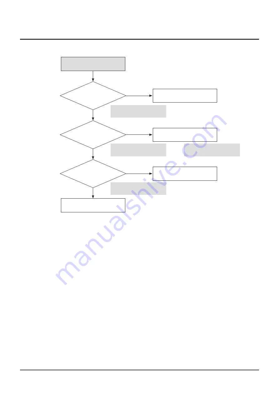
NO Power Detected
(Stand by LED OFF)
F1S01 is normal?
C1S05
voltage
is normal voltage?
Switching
operation
of IC1S10 is normal?
Change the SMPS PCB
Change fuse.
Change BD1.
Change IC1S10.
No
Yes
No
No
Yes
Yes
Refer to a pattern
image of Table 4-1
Refer to a pattern
image of Table 4-1
Refer to a pattern
image of Table 4-1
Refer to a pattern
image of Table 4-1
Summary of Contents for BD-C8200
Page 9: ...Samsung Electronics 1 7 Precautions M E M O ...
Page 23: ...Product Specification 2 14 Samsung Electronics M E M O ...
Page 38: ...Samsung Electronics 3 15 Disassembly and Reassembly M E M O ...
Page 81: ...Exploded Views and Parts List Samsung Electronics 5 17 M E M O ...
Page 83: ...6 2 Samsung Electronics PCB Diagrams 6 1 Wiring Diagram ...
Page 89: ...6 8 Samsung Electronics PCB Diagrams IC803 IC1006 CONDUCTOR SIDE ...
Page 91: ...6 10 Samsung Electronics PCB Diagrams CONDUCTOR SIDE ...
Page 93: ...6 12 Samsung Electronics PCB Diagrams CONDUCTOR SIDE ...
Page 94: ...Samsung Electronics 6 13 PCB Diagrams 6 5 Deck LED PCB IC1 COMPONENT SIDE ...
Page 95: ...6 14 Samsung Electronics PCB Diagrams CN1 CN2 CONDUCTOR SIDE ...
Page 96: ...Samsung Electronics 6 15 PCB Diagrams 6 6 HDD LED PCB CN1 COMPONENT SIDE ...
Page 97: ...6 16 Samsung Electronics PCB Diagrams CONDUCTOR SIDE ...
Page 98: ...Samsung Electronics 6 17 PCB Diagrams 6 7 Touch Key PCB COMPONENT SIDE CN1 CONDUCTOR SIDE ...
Page 99: ...6 18 Samsung Electronics PCB Diagrams 6 8 USB PCB COMPONENT SIDE CONDUCTOR SIDE USCN ...
Page 100: ...Samsung Electronics 6 19 PCB Diagrams M E M O ...
Page 128: ...M E M O 7 28 Samsung Electronics Schematic Diagrams ...


