Disassembly and Reassembly
3-10
Samsung Electronics
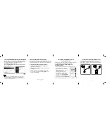
3-3-2 Ass'y Traverse Deck Removal
1) Disconnect the Spindle Motor FFC
q
from Connector(pin 4)
w
.
2) Disconnect Feeding Motor FPC
e
from Connector(pin 4)
r
.
3) Remove the 3 Screws
t
.
4) Lift up the Ass'y Traverse Deck
y
.
5) Remove the FFC Deck
u
.
Fig. 3-9 Ass'y Traverse Deck Removal
r
CONNECTOR
(4PIN)
u
FFC DECK
(14PIN)
w
CONNECTOR
(4PIN)
t
3 SCREWS
(2x5)
y
ASS'Y TRAVERSE
DECK
q
SPINDLE MOTOR
FFC
e
FEEDING MOTOR
FPC
(BOTTOM VIEW)
Summary of Contents for BD-P4600
Page 9: ...Samsung Electronics 1 7 Precautions M E M O ...
Page 18: ...Samsung Electronics 2 9 Product Specification M E M O ...
Page 31: ...Samsung Electronics 3 13 Disassembly and Reassembly M E M O ...
Page 54: ...Samsung Electronics 4 23 Trouble Shooting M E M O ...
Page 71: ...6 2 Samsung Electronics PCB Diagrams 6 1 Wiring Diagram ...
Page 74: ...Samsung Electronics 6 5 PCB Diagrams 6 3 VFD PCB CON4 CON2 COMPONENT SIDE ...
Page 75: ...6 6 Samsung Electronics PCB Diagrams VFD2 CONDUCTOR SIDE ...
Page 77: ...6 8 Samsung Electronics PCB Diagrams 6 5 USB PCB COMPONENT SIDE CONDUCTOR SIDE ...
Page 78: ...Samsung Electronics 6 9 PCB Diagrams 6 6 Remocon PCB COMPONENT SIDE CONDUCTOR SIDE ...
Page 79: ...6 10 Samsung Electronics PCB Diagrams M E M O ...
Page 101: ...7 22 Samsung Electronics Schematic Diagrams M E M O ...


