12_ introduction
introduction
rear View
POWER
VIDEO
1
3
2
4
5
6
7
8
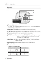
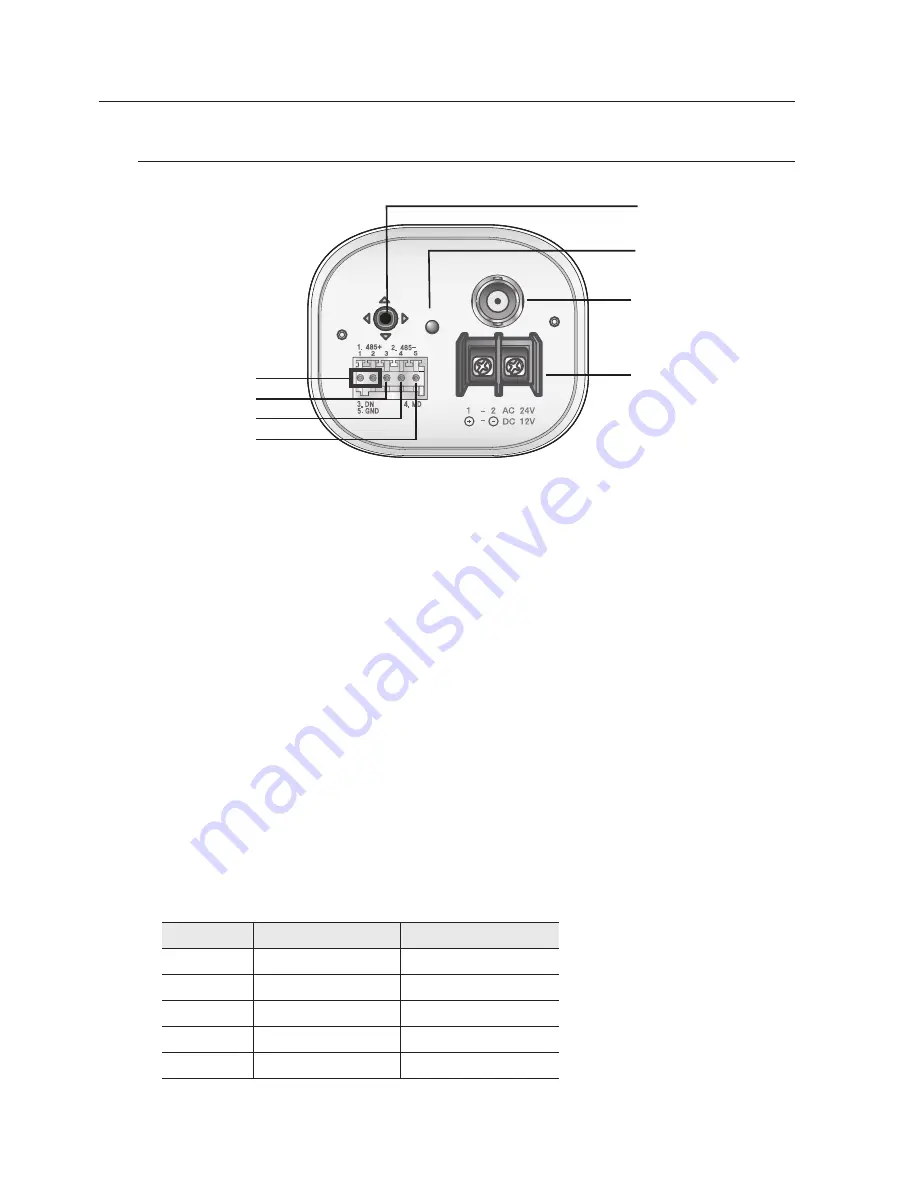
1
function setup switch
Display the menu on the screen and move the cursor to four directions to confirm ststus
or after changing a selected item.
2
Power lED :
This lamp is lit when the camera is receiving power normally.
3
Video ouT Terminal :
Sends video signal and connects to the video input terminal of the monitor.
4
Power input terminal :
Connect the designated power supplies.
5
rs-485 Control Port :
You can control SETUP MENU through this port by using
external controllers like a Remote controller that RS-485
Communication is supported.
6
D & n input Port :
You can switch to Day & Night Mode by connecting an external
signal to this port.
7
mD output Port :
Motion detection signals are output through this port.
8
ground terminal
Num
Name
I/O Direction
1
RS-485+
I/O
2
RS-485-
I/O
3
DN
I
4
MD
O
5
GND
-
※
External I / O port configuration

