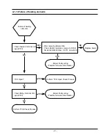
background image

- 50 -

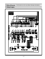
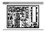
8. Schematic Diagram

TEMP SENSOR

LEVEL

Date Changed

TEMP SENSOR

INTERRUPT

Time Changed

STEAM TEMP

Engineer

OSCILLATOR

RELAY

of

CONTROL

SAMSUNG ELECTRONICS

DIVIDER &

RESET

TITLE

416, Maetan-3Dong, Yeongtong-Gu,

N/P SINGLE

LATCH

TEMP SENSOR

PCB TEMP

DISPLAY PCB

OVP

PYROLYTIC

Drawn by

PYROLYTIC TWIN

TEMP SENSOR

R&D CHK

WATER

Changed by

MODULE

Suwon-Si, Gyeonggi-Do, KOREA 443-742

EEP ROM

MEAT PROBE

N/P TWIN

On board writing

DOC CTRL CHK

MFG ENGR CHK

Drawing Number

Sheet

QA CHK

REV

1

1

0

2

 ,

N

A

J


7

1

N

O

E

J

_

S

M

09:00 AM

MS_JEON

MS_JEON


1

1

24" OVEN_MD

A2

Size

-TWIN & PYROLYTIC

POWER SUPPLY

100K

R305

R313

10K

TTC05103K

TH901

+5V

D213

MM4148

KIA358F

VCC=+6V,GND=DGND

IC401

5

+

6

-

7

OUT

RY203

DU12D1-1P

TR217

KRC246

16.000MHz

XTL1

TR203

KRC246

TLP-181

PC102

MM4148

D202

ZD101

UZ5.1B

R105

KRC246

TR211

2K

KRC246

10uF

C103

TR221

4.7uF

EM518

D01

+5V

C01

PC101

TLP-181

C109

470uF

R101

47K

R308

1K

100nF

C04

DF06S

BD101

RY201

DU12D1-1P

1K

D02

EM518

R111

78L05

IC02

MM4148

D212

R201

2K

R40

6

2K

+5V

+12V

TR01

KRA226

+5V

R801

13K

470K

R07

+5V

R317

2K

C117 12pF

C102

2K

R902

10uF

1N4007

D101

+5V

C105

10uF

D304

MM4148

12pF

1K

R08

C108

C116

VCC

VEE

470uF

VCC

VEE

IC302

KIA75S358

KIA75S358

IC303

+12V

10K

R03

KRC246

TR201

KRC246

TR214

VREFH

3

X1

30

X2

28

C305

10nF

40

81

82

83

84

21

70

75

76

RESET

32

43

RXD1

24

SCL0

78

SDA0

77

42

TXD1

23

9

10

89

14

63

67

68

41

19

22

62

18

11

33

34

39

2

7

8

1

92

100

99

91

98

90

97

93

94

80

95

96

25

20

73

74

71

72

6

79

58

61

57

56

55

87

69

88

45

44

46

51

50

49

48

47

59

60

52

15

16

17

13

12

AM1

31

AVCC

5

AVSS

4

DVCC

27

DVCC1

66

DVCC2

85

DVSS

29

DVSS1

64

DVSS2

86

EMU0

35

EMU1

36

37

38

NMI

65

54

53

IC101

TMP91FW60FG

AM0

26

+5V

MM4148

D201

R803

2K

470uF

10nF

C111

C304

RY213

TR207

KRC246

M

P

G5T-1A-ASI-12VDC

10uF

C302

SSR202

AQG22212

1uF

C901

D206

MM4148

6

8

9

10

MM4148

D203

ST101

1

2

3

4

5

D208

MM4148

ST-ALCD

DU12D1-1P

RY202

R40

4

2K

R10

R302

26.1K

1K

RY205

DU12D1-1P

R113

2K

KRC246

TR219

3.01K

R319

R503

2K

R311

2K

+5V

C110

470uF

R312

26.1K

+5V

+12V

470

R09

TR216

KRA226

3

+

-

2

OUT

1

MM4148

D209

VCC=+6V,GND=DGND

IC401

KIA358F

MM4148

D214

+12V

D303

MM4148

+5V

D204

MM4148

1
2

3
4

5
6

7
8

CN40

1

SMW250-08_WHT

DU12D1-1P

RY206

C115

100nF

100nF

1.2M

R107

C106

2K

100nF

C701

R701

12K

R06

47

R05

+5V

+5V

+5V

3

-

2

OUT

1

10K

R02

+5V

IC402
VCC=+6V,GND=DGND

KIA358F

+

80.6K

R502

MM4148

D302

2K

R112

7033P

IC105

47K

R102

R409

2K

200K

R414

Vss

7

WP

10K

R307

1

A0

2

A1

3

A2

6

SCL

5

SDA

8

Vcc

4

IC601

24C04

TR206

KRC246

1K

R314

D207

MM4148

In

2

Ire

1

Isw

3

Out

5

RC

6

Thr

8

Vcc

+5V

LM331N

IC01

4

Gnd

7

2
4

3

IC104

KIA7812API

CN302 SMW250-04_BLU

1

D105

1N4007

R402

2K

2K

R405

+5V

R321

D301

MM4148

R306

+5V

+5V

2K

470

MM4148

D205

D210

MM4148

1

3

5

7

9

+5V

CN201 SMW250-09A_RED

2K

R325

TR202

KRC246

KRC246

TR215

ZNR101

560V

TVR14561

TR102

KRC246

R41

3

200K

C306

200K

R412

10uF

C202

10nF

+6V

R103

47K

3

4
5

6

R901

5.1K

SMW250-06(WHT)

CN301

1

2

R702

330

TR101

KRA226

RY211

G5T-1A-ASI-12VDC

G5T-1A-ASI-12VDC

RY210

SMW250-04_WHT

CN501

4
2

1
3

T9AS1D22-12

D215

MM4148

RY207

G5T-1A-ASI-12VDC

RY215

2K

R410

100K

R318

6
7

SMW250-07_WHT

CN402

2

1
3

4
5

150K

30.1K

R316

+5V

R108

1

3

KRC246

TR205

CN204 SMW250-03A_RED

8

7
6

9
3

SMW250-09(WHT)

CN102

1
2

4

5

A

C

100nF

D104

MBRF5100

R11

470K

C112

R12

10K

LF-2CTOP

L101

1

2

3

4

2K

R320

DU12D1-1P

RY204

100nF

C307

12.7K

R315

10uF

C301

2K

R114

+5V

IC103

KIA78D05PI

UF4007

D102

KRC246

TR208

R322

100K

R304

1.87K

+5V

1nF

C114

3.01K

R323

26.1K

R301

2K

R324

2K

R408

R802

80.6K

+6V

R106

20K

TR218

KRC246

R41

1

200K

2K

R403

TR213

MM4148

D211

KRC246

M

P

C03

10uF

AQG22212

SSR203

VCC

VEE

1nF

C104

+5V

KIA75S393F

IC301

1uF

C02

RY209

G5T-1A-ASI-12VDC

KRC246

TR209

220

R110

C

2.2nF

C107

MBRF5100

D103

A

3

2
1

1nF

C05

CN801 SMW250-03_WHT

+6V

R407

2K

5

7

TR222

KRC246

CN202 SMW250-07A_RED

1

3

R116

TR210

KRC246

M

P

47K

AQG22212

SSR201

+5V

RY214

G5T-1A-ASI-12VDC

R310

30.1K

R303

10K

2

3
4

100K

R04

CN203 SMW250-04_RED

1

47K

R104

10nF

C201

RY212

G5T-1A-ASI-12VDC

G5T-1A-ASI-12VDC

RY208

+5V

C601

100nF

12K

R109

TR204

KRC246

1
2

3
6

CN701

SMW200-06P

5
4

+5V

R309

12.7K

TLP-181

PC01

6

4

1

3

R401

2K

R11

5

47K

+

5

6

-

7

OUT

470K

R01

KIA358F

IC402
VCC=+6V,GND=DGND

13K

R501

KRC246

10nF

C303

TR212

10uF

C113

100nF

270M

PTC101

S6

7

S7

S8 8

C101

TNY276P

B 2

4 D

1

E

S5

5

6

IC102

+5V

TR220

KRC246

TEST-1

TEST-2

2K

R601

OVP

NEUTRAL

LIVE-2

LIVE-2

LIVE-2

LIVE

EMU0

EMU0

DATA

STAND-BY

S-LEVEL

W-H

WH

WM

W-M

W-L

SL

WL

RXD
TXD
SCL
SDA

WAKE-UP
TOGGLE

BOT-HT

STEAM-HT

GRILL-SUB

GRILL-MAIN

OPTION

W-VALVE

WH

WL

SL

WM

STEAM-TEMP

SOURCE

STEAM-TEMP

S-U

PCB-TEMP

AD-IN-U

U-BAND-2

L-BAND-2

STEAM-HT

OPTION

W-M

DV-SW

RXD1
TXD1

RESET

UPPER-HT

AD_L

AD_U

RESET

OVP

INT

X2

WAKE-UP

RXD

SCL

TXD1

LOWER-HT

BOT-HT

GRILL-MAIN

LOWER-FAN

LATCH-CLOSE

LOWER-LP

COOLING

LATCH-2

DOOR-SW

L-BAND-1

CLK

S-LEVEL

W-H

W-L

STAND-BY

LATCH-1

SIDE-RACK

RXD1

SDA

TXD

X1

L-BAND-2

L-BAND-1

U-BAND-2

U-BAND-1

AD-IN-L

AD-IN-U

INT

LATCH-OPEN

W-VALVE

UPPER-HT

GRILL-SUB

UPPER-FAN

SOURCE

SPIT

W-PUMP

UPPER-LP

AD-IN-L

PROBE

S-L

U-BAND-1

TOGGLE

LIVE

NEUTRAL

LATCH-1

LATCH-2

SIDE-RACK

DOOR-SW

DATA

CLK

PROBE

X2

X1

AD_U

COOLING

SPIT

W-PUMP

LATCH-OPEN

LOWER-LP

UPPER-LP

LOWER-FAN

UPPER-FAN

LOWER-HT

LATCH-CLOSE

S-U

AD_U

LATCH-CONTROL

S-L

AD_L

LATCH-CONTROL

RESET

DV-SW

AD_U

PCB-TEMP

AD_L

8-1 Schematic Diagram 

Summary of Contents for BQ1AD4T013/XEF

Page 1: ...TS 1 Precaution 2 Product Specification 3 Disassembly and Reassembly 4 Troubleshooting 5 Exploded Views and Parts List 6 PCB Diagrams 7 Wiring Diagrams 8 Schematic Diagrams BASIC BQ1AQ4T013 MODEL BQ1AD4T013 MODEL CODE BQ1AD4T013 XEF ...

Page 2: ...r sub 19 3 13 Replacement of Motor Fan Cooling 20 3 14 Replacement of Duct Cover Bracket Spring Duct Ceramic Filter 20 3 15 Replacement of Motor Convection 21 3 16 Replacement of Heater Convection twin 22 3 17 Replacement of Assy Partition S W 22 3 18 Replacement of Thermostat 23 3 19 Replacement of Terminal Block 23 3 20 Replacement of Sensor Thermistor 23 3 21 Replacement of Heater Grill 24 3 22...

Page 3: ... any of the B voltage interlocks Do not apply AC power to the unit or any of its assem blies unless all solid state heat sinks are correctly installed 9 Some semiconductor solid state devices are easily damaged by static electricity Such compo nents are called Electrostatically Sensitive Devices ESDs Examples include integrated circuits and field effect transistors Immediately before handling any s...

Page 4: ...n Tact Dial Tact Dial Display 2 Layer LED 2 Layer LED Cleaning Method Oven Steam Self Descaling Steam Catalytic Descaling Heater Fixed Drop down Electric Features Oven Temp Ranges Single 40 300 C 300 C Grill only 40 270 C 270 C Grill only Upper or Lower 170 250 C 170 250 C Grill Heater In Out 1600W 1100W 1600W 1100W Bottom Heater 1100W 1100W Convection Heater Upper Lower 1200W 1200W 1200W 1200W En...

Page 5: ...heat convection Yes Yes 3 Large grill Yes Yes LOWER Mode 1 Convection Yes Yes 2 Bottom heat convection Yes Yes 3 Steam cook No No 4 Steam assist cook Yes Yes Control Features Clock Yes Yes Child Safety Lock Yes Hidden Yes Hidden Sound On Off Yes Hidden Yes Hidden Count Timer Yes Yes Cook Time Yes Yes End Time Yes Yes Oven Temp Yes Yes Steam Cleaning Yes Yes Self Cleaning Yes Yes Language Option No...

Page 6: ...ollowing accessories are provided with your oven Description Code No Q ty Rack wire DG59 00001A 1 RACK WIRE ROAST DG59 00004A 1 Front tray Baking a DG63 00012A 1 Front tray Baking B DG63 00011A 1 Assy partition DG97 00015A 1 ...

Page 7: ...al and Reassembly Tool 1 Tool Nut Driver 2 Type 7mm 3 Remarks Heater bracket Nut 1 Tool Nut Driver 2 Type 9mm 3 Remarks Convection Fan Nut 1 Tool Longnose 2 Remarks Tube Clamp You must remove it before the repair 3 2 Replacement of Case upper Cover back ...

Page 8: ... 3 Replacement the Tube Parts Explaination Photo Explaination Tube 1 Prepare long nose to remove the Tube clamp 2 Grab the Tube clamp with long nose 3 remove the Tube clamp 4 remove the Tube The Assembly is reverse order of disjointing ...

Page 9: ... both hinges 2 With both hands grasp the middle sides of the oven door 3 Rotate the door by approx 70degree until the hinges can be taken out completely from the hinges holes The Assembly is reverse order of disjointing 3 Disassembly and Reassembly 3 4 Replacement of Door Assembly ...

Page 10: ...edges of the front sheet Parts Explaination Photo Explaination Door Glass Screw Screw Screw Screw Door bracket Door bracket Glass 1 Glass 1 Cover Duct Cover Duct Cover Duct Cover Duct 1 Remove the two screws of the left and right sides of the door 2 Take off the two cover duct and door bracket Glass 1 Glass 1 Glass 1 Printing 3 Detach the inner glass 1 number 1 from the door When assembly the inne...

Page 11: ...ss cap 5 Replace the glass cap Lamp Glass cap Sheet ring Metal ring The Assembly is reverse order of disjointing Parts Explaination Photo Explaination Lamp Bulb 1 To remove the glass cover hold the lower end with one hand insert a flat sharp implement such as a table knife between the glass and the frame and pop out the cover 2 If necessary replace the halogen bulb with a 25 40 watt 230 V 300 C he...

Page 12: ...rts Assy Display Assy Knob Dial Encoder Parts Pump Motor Assy Inlet Explaination Photo Explaination 1 Remove one connector from the main pcb 2 Remove two Tubes and one connector at assy inlet 3 Remove 3 screws at both sides and top inside of assy control box lift up assy control box and pull forward to separate The Assembly is reverse order of disjointing ...

Page 13: ... 11 3 8 Replacement of Assy Control Box Continued Remove 2 screws Remove 11 screws Remove 4 screws ...

Page 14: ... Tube Steam Module Parts Explaination Photo Explaination Tube Steam Module 1 Remove the control box 2 Remove the 3 tubes 3 Remove the 2 connectors and 4 hook 4 Remove the 4 screws The Assembly is reverse order of disjointing ...

Page 15: ... 13 3 9 Replacement of Tube Steam Module Continued Parts Explaination Photo Explaination Tube Steam Module 5 Remove the Pump Motor 6 Remove 2 rubbers The Assembly is reverse order of disjointing ...

Page 16: ... Module 1 Seperate the wire harness from the hook on assy steam module and separate the 1 tube from assy steam generator 2 Remove 7 connectors and 2 TCO from the assy steam generator Lower Lamp is optional 3 Seperate the 2 tubes 4 Remove 5 screws The Assembly is reverse order of disjointing ...

Page 17: ...ate from oven Seperate the cover upper steam There are totally 4 hook that each has different direction 6 Seperate right and up side hook first 7 Seperate left and up side hook also 8 Seperate last 2 hook 3 10 Replacement of Assy Steam Module Continued The Assembly is reverse order of disjointing ...

Page 18: ...crewdriver And then remove the assy steam generator 11 Seperate the right side hook by using a flat head screwdriver And then remove the water valve 12 Seperate the 4 hook by using a flat head screwdriver And then remove the assy water tank 3 10 Replacement of Assy Steam Module Continued The Assembly is reverse order of disjointing ...

Page 19: ...int of assy water tank and check the right assembly with hook Water valve 1 Insert left side of water valve into hook 2 Press the right side of water valve Assy Steam generator 1 Insert left side of assy steam generator into hook 3 11 Assembly for Main Assy Steam module part ...

Page 20: ...ination Assy Steam generator 2 Press the right side of assy steam generator Connectors and Assy steam module 1 Check the right position between assy steam module hole and connector 3 11 Assembly for Main Assy Steam module part Continued ...

Page 21: ... 19 Parts Explaination Photo Explaination Assy generator sub 1 Remove 2 connectors 2 Remove the 2 tubes and 2 screws 3 12 Replacement of Assy generator sub ...

Page 22: ...Spring Duct Ceramic Filter Parts Explaination Photo Explaination Fan Cooling 1 Remove two screws and turn toward the clockwise to separate Parts Explaination Photo Explaination Fan Cooling 1 Remove 6 screws from ass y cover cooling motor The Assembly is reverse order of disjointing ...

Page 23: ...n convection and fan convection 4 Remove two connector from convection motor 5 Remove turn toward the counter clockwise to separate Reference Convection fan is turn in the opposite direction each other for improvement cook performance Upper fan is turn in counter clockwise direction Lower fan is fan turn in clockwise direction therefor convection fan direction and netflange are opposited each othe...

Page 24: ...e two screws securing heater convection twin at the rear 3 Pull the securing bracket at the left forward and pull it toward the left to separate heater convection twin 3 17 Replacement of Assy Partition S W Parts Explaination Photo Explaination Partition S W 1 Remove a connector 2 Remove two screws The Assembly is reverse order of disjointing ...

Page 25: ... three screws 3 18 Replacement of Thermostat 3 19 Replacement of Terminal Block Parts Explaination Photo Explaination Thermostat 1 Unfold one point Parts Explaination Photo Explaination Sensor Thermistor 1 Remove one screws 3 20 Replacement of Sensor Thermistor The Assembly is reverse order of disjointing ...

Page 26: ...orward to separate it 3 21 Replacement of Heater Grill Parts Explaination Photo Explaination Heater Grill 1 Remove the four connectors 2 Remove each nut frange at right and left sides 3 Turn the upper nut circular inside the cavity to the counterclockwise to release pull heater girll forward to separate The Assembly is reverse order of disjointing ...

Page 27: ... 25 3 23 Replacement of Assy PCB Parts Main PCB Parts Explaination Photo Explaination Assy PCB Parts Main PCB 1 Remove a screw 2 Seperate 3 hook The Assembly is reverse order of disjointing ...

Page 28: ...r sensor short Cooling motor sensor short Steam generator sensor short Sensor Short Error It occurs due to a defective sensor misplaced wires a defective PCB It may occur when the ambient temperature falls under 5 C 4 1 2 Safety Error Error Code Gerneral Function Solution Page Overtime Temp Time 100 C 16 hours 105 C 240 C 8 hours 245 C 4 hours This error occurs when the oven works during CUT OFF T...

Page 29: ... of sensor s failure Excess of cooking compart ment s temperature This error occur immediately after the temperature of cooking compartment reaches 350 C This error occurs when a fire occurs inside cooking compartment or the temperature cannot be con trolled because of sensor s failure Cooling motor lock sensed This error occurs when the temperature sensor on the Main PCB senses abnormal temperatu...

Page 30: ... the sensor wire connected properly Does the voltage change as the humidity temperature and weight change Replace the sensor Check if the sensor wire is damaged if the housing is loose and if the sensor and the wire are properly connected Check if the voltage of the GND and sensor changes using a digital multi meter by forcefully changing the humidity temperature and weight Connect the sensor Conn...

Page 31: ... and weight Check if the sensor and related parts such as the connector or soldering parts are slightly shorted Remove the shorted part of the temperature sensor Remove any foreign Substance from the shorted part YES NO YES YES NO NO YES NO Sensor Short Error E 28 E 2A E 2C E 72 Is the sensor shorted The sensor is out of order Replace the sensor Perform the operation again and check if it is worki...

Page 32: ... again and check if it is working properly S W Error Is a specific key not recognized Is the key recognized intermittently The membrane is defective Replace the Control Panel Is the key not recognized at all After Power On does the symptom continue Replace the PCB 4 1 5 SE ...

Page 33: ...or the corresponding internal temperature Is it temperature 100 C in oven Is it temperature 105 C 240 C in oven Is it temperature 245 C in oven Does same error arise S W Error S W Error Does same error arise Does same error arise Has it worked for 8 hours continuously Has it worked for 6 hours continuously Has it worked for 4 hours continuously Turn the oven off and let it cool sufficiently After ...

Page 34: ...Is divider inserted Is it Upper Lower Mode Is the Divider detection S W out of order Is the Divider detection S W connected properly Are the connections in the Main PCB normal Connect correctly Connect correctly wire S W Error After Power On does the symptom continue Replace the PCB Perform the operation again and check if it is working properly Remove the Divider 4 1 7 dE ...

Page 35: ...ir the short circuit Is the temperature of the PCB over 90 C An E 2b error occurred Insert the temperature sensor An E 0b error occurred Check the Motor drive part Is the Cooling Motor rotating The temperature sensor is out of order Replace the temperature sensor Perform the operation again and check if it is working properly S W Error After Power On does the symptom continue Replace the PCB 4 1 8...

Page 36: ...YES NO YES NO Preheating Error E 08 Is the heater temperature very low Is the temperature sensor connected properly Is the resistance between the heater terminals more then a few MΩ Check the heater related drive part Replace the heater Reconnect the temperature sensor properly Replace the heater Does the heater work S W Error After Power On does the symptom continue Replace the PCB Perform the op...

Page 37: ...s relay and sensor part YES NO NO YES Steam generator temp Error E 73 Is the PCB part shorted Temp sensor malfunction Replace the Assy steam generator Does the steam generator temp sensor work Replace the PCB Perform the operation again and check if it is working properly 4 1 10 E 73 ...

Page 38: ...rror E 78 Does Water Valve work Connect steam generator water level connector Replace the Water Valve Is steam generator water level connector disconnected Perform the operation again and check if it is working properly YES NO S W Error After Power On does the symptom continue Replace the PCB 4 1 12 E 78 ...

Page 39: ...d over 320 degrees Has the oven internal temperature reached over 350 degrees Is the temperature sensor connectivity normal Is the Heater connectivity normal An E 09 error occurred An E 24 E 0A error occurred Reconnect the temperature sensor properly Check and repair the heater drive part if necessary S W Error After Power On does the symptom continue Replace the PCB Perform the operation again an...

Page 40: ...ES YES YES Check terminal block voltage 230V Reset The circuit braker or Check main power NO TCO open Check main TCO Convection TCO Replace TCO NO Check the input voltage of PCB SMPS input checkpoint 230V Repair Faulty wiring NO 4 1 11 Power Failure ...

Page 41: ...tor Conveclion Motor check Motor Connect wire Remove Motor Resistor check Cooling motor 238Ω Convection Motor 218Ω Motor Terminal Voltage check Replace Motor PCB SMPS Input Voltage check input check point 5V 230V Repair Faulty wiring PCB SMPS output Voltage check output check point 5V 12C Replace PCB PCB Relay contact short check Replace PCB YES NO NO YES YES NO YES YES NO YES NO NO 4 1 12 TCO Ope...

Page 42: ... is appro priate for each relay Reset the circuit braker or check main power Repair Faulty wiring or PCB check Check Terminal block voltage 230V Replace Safety Relay Do all relays operate After Lamp On Safety Relay Contact point ON 12V Check the operating Base voltage 0V of Safety Relay Replace PCB YES NO YES NO NO NO Check fuse protecting SMPS Replace PCB YES YES YES YES NO YES NO NO YES Replace ...

Page 43: ...ontact failure Failure of heating elements Perform PCB Check Process TCO Open Check Relay Terminal Volt age 230V Replace heater After removing Heater Wire Check Heater resistance Large G 32 8Ω Small G 48 6Ω Bottom 48 1Ω Conv 44Ω Check heater s terminal volt age 230V YES NO YES YES YES NO NO NO 4 1 14 Failure of heating elements ...

Page 44: ...032 H451 M300 W002 M253 H111 M242 H051 H052 G005 M017 M264 B028 B048 M251 H106 H107 H094 M229 P186 H050 W006 M482 P329 M236 H005 H057 H048 P229 U029 Z031 P225 U028 H049 H058 H048 H049 C003 C195 C003 P284 M262 H111 M013 M032 M003 P214 D120 M241 M007 P282 M392 M258 M260 M261 M302 H008 M294 M293 M370 M015 M279 M248 U013 M265 M249 M250 M277 ...

Page 45: ... 43 5 2 Main Parts List SNA SERVICE NOT AVAILABLE No Code No Description Specification Q ty SA SNA Remark M260 DG61 00056A SUPPORT MOTOR COOLING PA66 GF15 BT63BSS 1 SA ...

Page 46: ... 44 5 2 Main Parts List No Code No Description Specification Q ty SA SNA Remark ...

Page 47: ... 45 5 3 Door Parts List SNA SERVICE NOT AVAILABLE No Code No Description Specification Q ty SA SNA Remark D105 V002 V002 D106 D109 P420 D049 D110 D113 D151 P421 D015 D019 D147 D049 ASSY DOOR ...

Page 48: ...arts List SNA SERVICE NOT AVAILABLE No Code No Description Specification Q ty SA SNA Remark C009 C236 C235 C074 C001 C048 C154 Y101 C082 C187 C360 C185 C360 C190 C197 C188 Y102 C187 C352 C188 C178 C082 ASSY CONTROL BOX ...

Page 49: ... 47 5 5 Standard Parts List SNA SERVICE NOT AVAILABLE LEV EL Code No Description Specification Q ty SA SNA Remark ...

Page 50: ... Lock motor connector A Terminal for Connecting with Door Lock motor 16 RY108 Uppwe lamp Relay Uppwe lamp control 6 CN106 Neutral upper lower lamp A Terminal for Connecting with Neutral upper lower lamp 17 RY109 Lower lamp Relay Lower lamp control 7 CN107 Spit Upper lower fan Cooling fan A Terminal for Connecting with Spit Upper lower fan Cooling fan 18 RY111 Spit Relay Spit Source 8 CN108 Door la...

Page 51: ... 49 7 Wiring Diagram This Document can not be used without Samsung s authorization 7 1 Wiring Diagram ...

Page 52: ...V LM331N IC01 4 Gnd 7 2 4 3 IC104 KIA7812API CN302 SMW250 04_BLU 1 D105 1N4007 R402 2K 2K R405 5V R321 D301 MM4148 R306 5V 5V 2K 470 MM4148 D205 D210 MM4148 1 3 5 7 9 5V CN201 SMW250 09A_RED 2K R325 TR202 KRC246 KRC246 TR215 ZNR101 560V TVR14561 TR102 KRC246 R413 200K C306 200K R412 10uF C202 10nF 6V R103 47K 3 4 5 6 R901 5 1K SMW250 06 WHT CN301 1 2 R702 330 TR101 KRA226 RY211 G5T 1A ASI 12VDC G5...

Page 53: ...domestic law GSPN Global Service Partner Network Contry Web Site North America service samsungportal com Latin America latin samsungportal com CIS cis samsungportal com Europe europe samsungportal com China china samsungportal com Asia asia samsungportal com Mideast Africa mea samsungportal com Samsung Electronics Co Ltd April 2011 Printed in Korea ...

Reviews: