background image

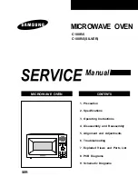
MICROWAVE OVEN

CONTENTS

MICROWAVE OVEN

1. Precaution

2. Specifications

3. Operating Instructions

4. Disassembly and Reassembly

5. Alignment and Adjustments

6. Troubleshooting

7. Exploded Views and Parts List

8. PCB Diagrams

9. Schematic Diagrams

Manual

C100R-5

C100R-5(SILVER)

SER

Summary of Contents for C100R-5

Page 1: ...OVEN 1 Precaution 2 Specifications 3 Operating Instructions 4 Disassembly and Reassembly 5 Alignment and Adjustments 6 Troubleshooting 7 Exploded Views and Parts List 8 PCB Diagrams 9 Schematic Diagrams Manual C100R 5 C100R 5 SILVER SER ...

Page 2: ...ronics Co Ltd November 2003 Printed in Korea Code No DE68 03334A This Service Manual is a property of Samsung Electronics Co Ltd Any unauthorized use of Manual can be punished under applicable International and or domestic law ...

Page 3: ...s and latches 5 evidence of dropping or abuse c Before turning on microwave power for any service test or inspection within the microwave generating compartments check the magnetron wave guide or transmission line and cavity for proper alignment integrity and connections d Any defective or misadjusted components in the interlock monitor door seal and microwave generation and transmission systems s...

Page 4: ... should remove their watches while repairing an MWO 11 To avoid any possible radiation hazard replace parts in accordance with the wiring diagram Also use only the exact replacements for the following parts Primary and secondary interlock switches interlock monitor switch 12 If the fuse is blown by the Interlock Monitor Switch Replace all of the following at the same time Primary door sensing swit...

Page 5: ...apacitor remains charged about 30 seconds after disconnection Short the negative terminal of the high voltage capacitor to to the oven chassis Use a screwdriver 3 High voltage is maintained within specified limits by close tolerance safety related components and adjustments If the high voltage exceeds the specified limits check each of the special components PRECAUTION There exists HIGH VOLTAGE EL...

Page 6: ...WER OPERATING FREQUENCY MAGNETRON COOLING METHOD OUTSIDE DIMENSIONS NET WEIGHT GROSS WEIGHT 99 MINUTES 230V 50Hz AC MICROWAVE 1 400W GRILL 1 300W CONVECTION 1 700W FROM 100 TO 900W 6 LEVEL POWER IEC 705 TEST PROCEDURE 2 450MHz OM75P 31 ERHN COOLING FAN MOTOR 517 W x 310 H x 511 D mm 19 0 kg 22 5 kg ...

Page 7: ... 310mm 216mm 511mm 3 Operating Instructions 3 1 Control Panel 3 2 Features External Views Door Ventilation Holes Light Safety Interlock Holes Control Panel Guide Roller Coupler Grill Rack Glass Plate Door Latches ...

Page 8: ... that its antenna does not hit any adjacent parts or it may be damaged NOTE2 When replacing the magnetron be sure to remount the magnetron gasket inthe correct position and make sure the gasket is in good condition 4 2 Replacement of High Voltage Transformer 1 Discharge the high voltage capacitor 2 Disconnect all the leads 3 Remove the mounting bolts 4 Reconnect the leads correctly and firmly PREC...

Page 9: ... C because it is fragile 4 3 3 Removal of Door E Following the procedure as shown in the figure insert and bend a thin metal plate between Door E and Door A until you hear the tick sound 1 Insertion depth of the thin metal plate should be 0 5mm or less 4 3 4 Removal of Key Door Spring Remove pin hinge from Door E Datach spring from Door E and key door 4 3 5RemovalofScreen Door Deco Door 1 Remove D...

Page 10: ...ther part such as the control circuit board blower motor or high voltage transformer is defective 4 5 Replacement of Drive Motor 1 Take out the glass tray guide roller from oven cavity disconnect power 2 Remove turn table motor cover from case bottom CAUTION Remove sharp edge after cover removal 3 Disconnect leads from motor 4 Remove the screws securing motor to bottom of over cavity and left out ...

Page 11: ... your body and avoid touching the touch control circuitry 2 Disconnect the connectors from the control circuit board 3 Remove screws securing the control box assembly 4 Lift up the control circuit board from right side and remove the hooks holding the control circuit board to the box assembly SCREWS ...

Page 12: ...te the magnetron from the circuit by disconnecting its leads 3 A continuity check across the magnetron filament terminals should indicate one ohm or less 4 A continuity check between each filament terminal and magnetron case should read open PRECAUTION 1 High voltage is present at the high voltage terminals during any cook cycle 2 It is neither necessary nor advisable to attempt measurement of the...

Page 13: ...ch to Latch Body consult the figure 2 No specific adjustment during installation of Primary switch and Monitor switch to the latch body is necessary 3 When mounting the Latch Body to the oven assembly adjust the Latch Body by moving it so that the oven door will not have any play in it Check for play in the door by pulling the door assembly Make sure that the latch keys move smoothly after adjustm...

Page 14: ...lation 4 When heating is finished stir the water again with the thermometer and measure the temperature T2 5 Subtract T1 from T2 This will give you the water temperature rise ଠT 6 The output power is obtained by the following formula Output Power 4 187 x 1000 x ଠT 0 88 x Mc x T2 T0 49 Heating Time sec 46 4 187 Coefficient for Water 1000 Water cc ଠT Temperature Rise T1 T2 Mc Cylindrical borosilicat...

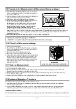
Page 15: ...ower level 4 Set survey meter dual ranges to 2 450MHz 5 Using the survey meter and spacer cone as described above measure near the opening of magnetron the surface of the air guide and the surface of the wave guide as shown in the following photo but avoid the high voltage components The reading should be less than 4mW cm2 5 11 Note on Measurement 1 Do not exceed the limited scale 2 The test probe...

Page 16: ...former NOTE2 Check adjustment of primary interlock monitor power relay door sensing switch NOTE 1 All of these switches must be replaced at the same time refer to adjustment instructions Check continuity of power relay contacts and if it has continuity replace power relay also NOTE 2 When H V Transformer is replaced check diode and magnetron also Oven does not accept key input Program 1 Key input ...

Page 17: ...CB main Loud buzzing noise can be heard 1 Loose fan and fan motor 2 Loose screws on H V Transformer 3 Shorted H V Diode Tighten screws of fan motor Tighten screws of H V Transformer Replace H V Diode Turntable motor does not rotate 1 Open or loose wiring of turntable motor 2 Defective turntable motor Replace turntable motor Oven stops operation during cooking 1 Open or loose wiring of primary inte...

Page 18: ...s M001 W006 W003 M035 M037 M005 M041 M043 MM105 MM103 MM104 M046 M047 M040 M039 M038 M049 T001 T017 M034 T010 T009 M051 M054 M053 M057 M048 M031 M113 M095 M009 M008 M010 M011 M013 H016 M015 W002 M017 M019 M023 M036 M004 M029 M016 M012 B018 B006 B001 B002 B009 ...

Page 19: ...A THERMOSTAT PW2N 520PB 160 60 250V 7 5A H 1 MGT M031 DE47 20009A THERMOSTAT PW2N 520PB 160 60 250V 7 5A H 1 M034 DE67 00182A COUPLER 5TH 1 0 PPS 1 M035 OM75P 31 ERHN ASSY MAGNETRON OM75P 31 ERHN 1 M037 DE63 00248A COVER AIR 5th 1 0 Convection Nylon 66 1 M038 DE26 00096A TRANS H V SHV EURO2 1 230V 50Hz 2350V 3 1 M039 2501 001015 C OIL 1 0uF 2100V BK 35X54X80 20mm 1 M040 DE61 50106A BRACKET HVC SEC...

Page 20: ...NGE LOWER WHT TN 5630T SSEC T2 3 26 77 1 D011 DE64 00547A KEY DOOR C100 NYLON 66 GV10 V0 1 D021 DE64 90160A DECORATION DOOR Y745STC S7A77 1 WHITE D021 DE64 90160G DECORATION DOOR C100 SL PC SILVER 1 SILVER D024 DE67 20184K SCREEN DOOR B CK920T TEMP GLASS T3 2 1 D043 DE63 00205A CUSHION SCREEN C115 PC T2 0 W12 L150 2 D047 DE94 01031A ASSY DOOR E SEALANT 5th 1 0 Convection 1 Ͳ Ί ʹ Έ ΥΙ ʹΠΟΧΖΔΥΚΠΟ WH...

Page 21: ... DE64 00375B BUTTON SELECT B C100 SL PC SILVER 1 BOARD PCB 1 SILVER C025 DE64 00370A KNOB CK95 VI PC PURE WHT 1 BO 1 WHITE C025 DE64 00370B KNOB C100 SL PC SILVER 1 BOARD PCB 1 SILVER C041 DE64 00374B BUTTON CANCEL C100 R BWT PC PURE WHT RUSSIA 1 WHITE C041 DE64 00374G BUTTON CANCEL C100R 5SL BWT PC SILVER RUSSIA 1 SILVER C043 DE64 00372B BUTTON DEFROST C100 R BWT PC PURE WHT RUSSIA 1 WHITE C043 D...

Page 22: ...LSTAR T0 6 W250 L250 1 H003 DE47 70077A HEATER CONVECTION SHC 118E1 1680W 1 H005 DE97 00472A ASSY COVER CASING 5th 1 0 Convection 1 H006 DE62 00029A ADIABATIC CASING C115 FINE GLASS WOOL T0 1 H007 DE72 30016A BUSH MOTOR MSWR3 L11 2 D5 6 RE 1300 1 H008 DE60 40026B WASHER PLAIN ID5 5 OD12 T1 0 SBC1 ZNC3 1 H011 DE60 40014B WASHER C MOTOR M16 T1 0 SECC ZNC3 1 H011 H002 H001 H002 H008 H007 H006 H004 H0...

Page 23: ...REW TAP TH FE FN TAP TH 2 4X8 2 C CEILING DE60 10122A SCREW TAP TH FE FN TAP TH 2 4X8 2 b heater DE60 10122A SCREW TAP TH FE FN TAP TH 2 4X8 4 c motor DE60 10122A SCREW TAP TH FE FN TAP TH 2 4X8 1 tco 6002 000170 SCREW TAPPING PH 2S M3 L6 ZPC YEL SWRCH 1 2 6002 000231 SCREW TAPPING TH 2S M4 L12 ZPC YEL SM20C 2 A C BACK 6002 000231 SCREW TAPPING TH 2S M4 L12 ZPC YEL SM20C 4 A CASING 6002 000231 SCR...

Page 24: ... ڈٻڌڍٻڈ 8 P C B Diagrams 8 1 P C B Diagrams This Document can not be used without Samsung s authorization ...

Page 25: ...REG 78L05 SOT 89 3P 185MIL PLASTIC 1 IC02 1404 000230 THERMISTOR PTC 27ohm 20 265V 1 5A 360mA BK 2 PTC1 C2 2007 000033 R CHIP 0ohm 5 1 4W TP 3216 14 J01 14 2007 000277 R CHIP 100Kohm 1 1 8W TP 2012 1 R13 2007 000300 R CHIP 10Kohm 5 1 8W TP 2012 6 R07 09 16 17 2007 000468 R CHIP 1Kohm 5 1 8W TP 2012 7 R01 03 05 10 14 15 2007 000671 R CHIP 2Kohm 5 1 8W TP 2012 2 R02 11 2007 000868 R CHIP 4 7Kohm 1 1...

Page 26: ...iagrams This Document can not be used without Samsung s authorization MAGNETRON FA F RED RED RED RED SYMBOL COLOR BRN BROWN BLK BLACK RED RED BLU BLUE WHT BLK HIGH VOLTAGE TRANSFORMER HIGH VOLTAGE CAPACITOR HIGH VOLTAGE DIODE TO CHASSIS H V FUSE ...

Reviews: