KS57C2308/P2308/C2316/P2316
SERIAL I/O INTERFACE
13-3
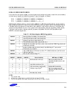
SERIAL I/O MODE REGISTER (SMOD)
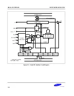
The serial I/O mode register, SMOD, is an 8-bit register that specifies the operation mode of the serial interface.
Its reset value is logical zero. SMOD is organized in two 4-bit registers, as follows:
FE0H
SMOD.3
SMOD.2
SMOD.1
SMOD.0
FE1H
SMOD.7
SMOD.6
SMOD.5
0
SMOD register settings enable you to select either MSB-first or LSB-first serial transmission, and to operate in
transmit-and-receive mode or receive-only mode. SMOD is a write-only register and can be addressed only by
8-bit RAM control instructions. One exception to this is SMOD.3, which can be written by a 1-bit RAM control
instruction. When SMOD.3 is set to 1, the contents of the serial interface interrupt request flag, IRQS, and the
3-bit serial clock counter are cleared, and SIO operations are initiated. When the SIO transmission starts,
SMOD.3 is cleared to logical zero.
Table 13-1. SIO Mode Register (SMOD) Organization
SMOD.0
0
Most significant bit (MSB) is transmitted first
1
Least significant bit (LSB) is transmitted first
SMOD.1
0
Receive-only mode; output buffer is off
1
Transmit-and-receive mode; output buffer is on
SMOD.2
0
Disable the data shifter and clock counter; retain contents of IRQS flag when serial
transmission is halted
1
Enable the data shifter and clock counter; set IRQS flag to "1" when serial
transmission is completed
SMOD.3
1
Clear IRQS flag and 3-bit clock counter to "0"; initiate transmission and then reset
this bit to logic zero
SMOD.4
0
Bit not used; value is always "0"
SMOD.7
SMOD.6
SMOD.5
Clock Selection
R/W Status of SBUF
0
0
0
External clock at
SCK
pin
SBUF is enabled when SIO
operation is halted or when
SCK
goes high.
0
0
1
Use TOL0 clock from TC0
0
1
–
CPU clock: fxx/4, fxx/8, fxx/64
Enable SBUF read/write
1
0
0
4.09 kHz clock: fxx/2
10
SBUF is enabled when SIO
operation is halted or when
SCK
goes high.
1
1
1
262 kHz clock: fxx/2
4
NOTES
:
1.
“fxx” = system clock.
2.
kHz frequency ratings assume a system clock (fxx) running at 4.19 MHz.
3.
The SIO clock selector circuit cannot select a fxx/2
4
clock if the CPU clock is fxx/64
.
Summary of Contents for C2316
Page 30: ...ADDRESS SPACES KS57C2308 P2308 C2316 P2316 2 22 NOTES ...
Page 168: ...SAM47 INSTRUCTION SET KS57C2308 P2308 C2316 P2316 5 94 NOTES ...
Page 170: ......
Page 206: ...POWER DOWN KS57C2308 P2308 C2316 P2316 8 8 NOTES ...
Page 210: ...RESET KS57C2308 P2308 C2316 P2316 9 4 NOTES ...
Page 222: ...I O PORTS KS57C2308 P2308 C2316 P2316 10 12 NOTES ...
Page 272: ...LCD CONTROLLER DRIVER KS57C2308 P2308 C2316 P2316 12 24 NOTES ...
Page 280: ...SERIAL I O INTERFACE KS57C2308 P2308 C2316 P2316 13 8 NOTES ...
Page 294: ...MECHANICAL DATA KS57C2308 P2308 C2316 P2316 15 2 NOTES ...
Page 310: ...KS57P2308 P2316 OTP KS57C2308 P2308 C2316 P2316 16 16 NOTES ...
Page 318: ......
Page 320: ......
Page 322: ......
Page 325: ......
Page 327: ......


