KS57C2308/P2308/C2316/P2316
KS57P2308/P2316 OTP
16-7
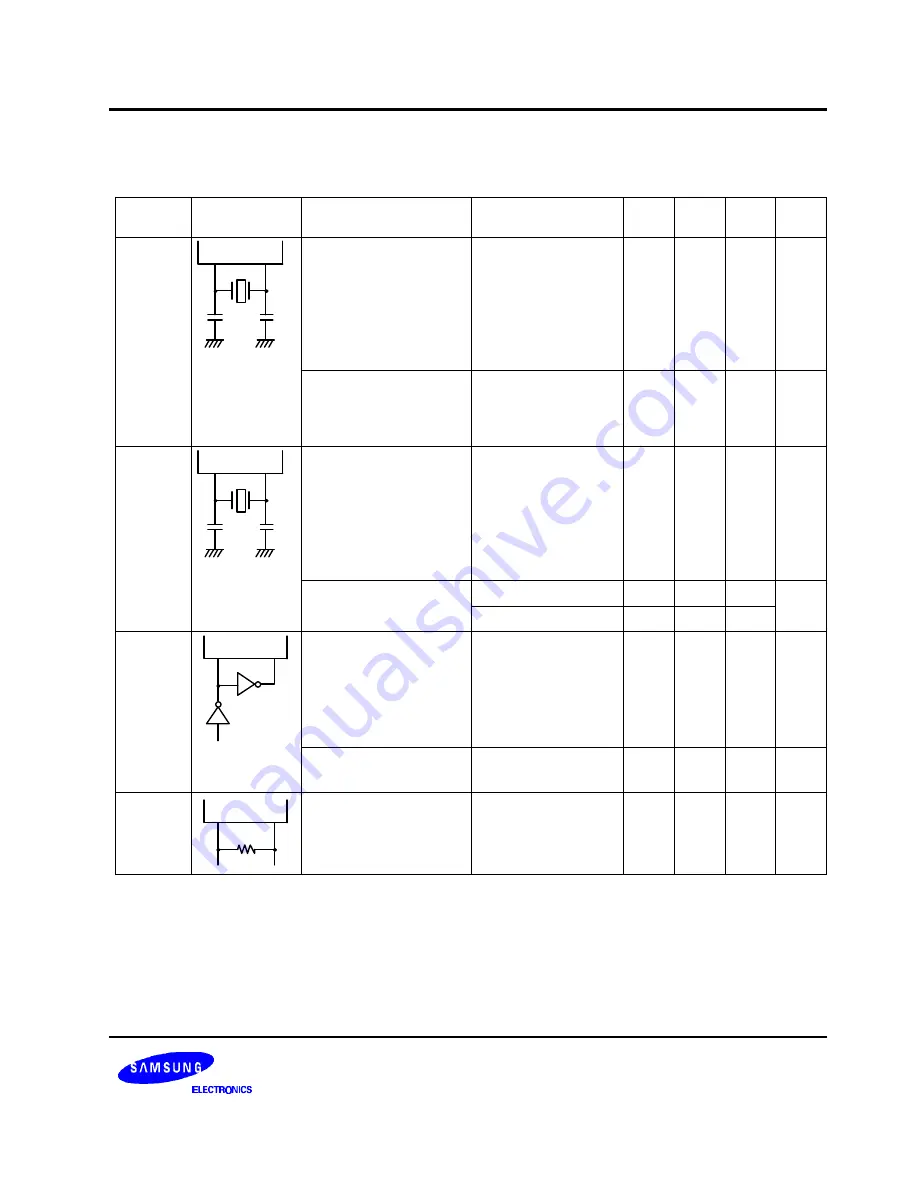
Table 16-6. Main System Clock Oscillator Characteristics
(T
A
= – 40
°
C + 85
°
C, V
DD
= 1.8 V to 5.5 V)
Oscillator
Clock
Configuration
Parameter
Test Condition
Min
Typ
Max
Units
Ceramic
Oscillator
X
IN
X
OUT
C1
C2
Oscillation frequency
(1)
–
0.4
–
6.0
MHz
Stabilization time
(2)
Stabilization occurs
when V
DD
is equal to
the minimum oscillator
voltage range.
–
–
4
ms
Crystal
Oscillator
C1
C2
X
IN
X
OUT
Oscillation frequency
(1)
–
0.4
–
6.0
MHz
Stabilization time
(2)
V
DD
= 4.5 V to 5.5 V
–
–
10
ms
V
DD
= 1.8 V to 4.5 V
–
–
30
External
Clock
X
IN
X
OUT
X
IN
input frequency
(1)
–
0.4
–
6.0
MHz
X
IN
input high and low
level width (t
XH
, t
XL
)
–
83.3
–
–
ns
RC
Oscillator
R
X
IN
X
OUT
Frequency
(1)
V
DD
= 5 V
R = 20 K
Ω
, V
DD
= 5 V
R = 38 K
Ω
, V
DD
= 3 V
0.4
–
2.0
1.0
2
MHz
NOTES:
1.
Oscillation frequency and X
IN
input frequency data are for oscillator characteristics only.
2.
Stabilization time is the interval required for oscillator stabilization after a power-on occurs, or when stop mode is
terminated.
Summary of Contents for C2316
Page 30: ...ADDRESS SPACES KS57C2308 P2308 C2316 P2316 2 22 NOTES ...
Page 168: ...SAM47 INSTRUCTION SET KS57C2308 P2308 C2316 P2316 5 94 NOTES ...
Page 170: ......
Page 206: ...POWER DOWN KS57C2308 P2308 C2316 P2316 8 8 NOTES ...
Page 210: ...RESET KS57C2308 P2308 C2316 P2316 9 4 NOTES ...
Page 222: ...I O PORTS KS57C2308 P2308 C2316 P2316 10 12 NOTES ...
Page 272: ...LCD CONTROLLER DRIVER KS57C2308 P2308 C2316 P2316 12 24 NOTES ...
Page 280: ...SERIAL I O INTERFACE KS57C2308 P2308 C2316 P2316 13 8 NOTES ...
Page 294: ...MECHANICAL DATA KS57C2308 P2308 C2316 P2316 15 2 NOTES ...
Page 310: ...KS57P2308 P2316 OTP KS57C2308 P2308 C2316 P2316 16 16 NOTES ...
Page 318: ......
Page 320: ......
Page 322: ......
Page 325: ......
Page 327: ......


