MEMORY MAP
KS57C2308/P2308/C2316/P2316
4-6
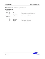
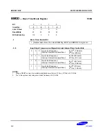
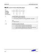
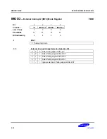
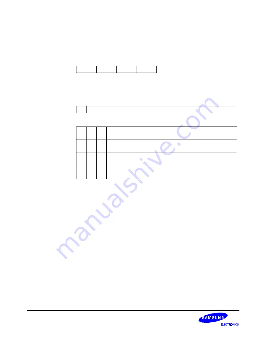
BMOD
— Basic Timer Mode Register
F85H
Bit
3
2
1
0
Identifier
.3
.2
.1
.0
RESET
Value
0
0
0
0
Read/Write
W
W
W
W
Bit Addressing
1/4
4
4
4
.3
Basic Timer Restart Bit
1
Restart basic timer, then clear IRQB flag, BCNT and BMOD.3 to logic zero
.2–.0
Input Clock Frequency and Signal Interrupt Interval Time Control Bits
0
0
0
Input clock frequency:
Interrupt interval time (wait time):
fxx/2
12
(1.02 kHz)
2
20
/fxx (250 ms)
0
1
1
Input clock frequency:
Interrupt interval time (wait time):
fxx/2
9
(8.18 kHz)
2
17
/fxx (31.3 ms)
1
0
1
Input clock frequency:
Interrupt interval time (wait time):
fxx/2
7
(32.7 kHz)
2
15
/fxx (7.82 ms)
1
1
1
Input clock frequency:
Interrupt interval time (wait time):
fxx/2
5
(131 kHz)
2
13
/fxx (1.95 ms)
NOTES
:
1.
When a RESET occurs, the oscillator stabilization wait time is 31.3 ms (217/fxx) at 4.19 MHz.
2.
“fxx” is the system clock rate given a clock frequency of 4.19 MHz.
Summary of Contents for C2316
Page 30: ...ADDRESS SPACES KS57C2308 P2308 C2316 P2316 2 22 NOTES ...
Page 168: ...SAM47 INSTRUCTION SET KS57C2308 P2308 C2316 P2316 5 94 NOTES ...
Page 170: ......
Page 206: ...POWER DOWN KS57C2308 P2308 C2316 P2316 8 8 NOTES ...
Page 210: ...RESET KS57C2308 P2308 C2316 P2316 9 4 NOTES ...
Page 222: ...I O PORTS KS57C2308 P2308 C2316 P2316 10 12 NOTES ...
Page 272: ...LCD CONTROLLER DRIVER KS57C2308 P2308 C2316 P2316 12 24 NOTES ...
Page 280: ...SERIAL I O INTERFACE KS57C2308 P2308 C2316 P2316 13 8 NOTES ...
Page 294: ...MECHANICAL DATA KS57C2308 P2308 C2316 P2316 15 2 NOTES ...
Page 310: ...KS57P2308 P2316 OTP KS57C2308 P2308 C2316 P2316 16 16 NOTES ...
Page 318: ......
Page 320: ......
Page 322: ......
Page 325: ......
Page 327: ......

