MEMORY MAP
KS57C2308/P2308/C2316/P2316
4-22
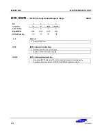
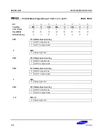
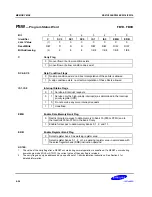
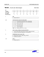
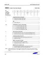
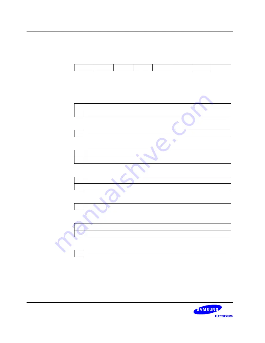
PMG2
— Port I/O Mode Flags (Group 2: Port 2, 4, 5, and 7)
FEDH, FECH
Bit
7
6
5
4
3
2
1
0
Identifier
PM7
“0”
PM5
PM4
“0”
PM2
“0”
“0”
RESET
Value
0
0
0
0
0
0
0
0
Read/Write
W
W
W
W
W
W
W
W
Bit Addressing
8
8
8
8
8
8
8
8
PM7
P7 I/O Mode Selection Flag
0
Set P7 to input mode
1
Set P7 to output mode
.6
Bit 6
0
Always logic zero
PM5
P5 I/O Mode Selection Flag
0
Set P5 to input mode
1
Set P5 to output mode
PM4
P4 I/O Mode Selection Flag
0
Set P4 to input mode
1
Set P4 to output mode
.3
Bit 3
0
Always logic zero
PM2
P2 I/O Mode Selection Flag
0
Set P2 to input mode
1
Set P2 to output mode
.1–.0
Bits 1–0
0
Always logic zero
Summary of Contents for C2316
Page 30: ...ADDRESS SPACES KS57C2308 P2308 C2316 P2316 2 22 NOTES ...
Page 168: ...SAM47 INSTRUCTION SET KS57C2308 P2308 C2316 P2316 5 94 NOTES ...
Page 170: ......
Page 206: ...POWER DOWN KS57C2308 P2308 C2316 P2316 8 8 NOTES ...
Page 210: ...RESET KS57C2308 P2308 C2316 P2316 9 4 NOTES ...
Page 222: ...I O PORTS KS57C2308 P2308 C2316 P2316 10 12 NOTES ...
Page 272: ...LCD CONTROLLER DRIVER KS57C2308 P2308 C2316 P2316 12 24 NOTES ...
Page 280: ...SERIAL I O INTERFACE KS57C2308 P2308 C2316 P2316 13 8 NOTES ...
Page 294: ...MECHANICAL DATA KS57C2308 P2308 C2316 P2316 15 2 NOTES ...
Page 310: ...KS57P2308 P2316 OTP KS57C2308 P2308 C2316 P2316 16 16 NOTES ...
Page 318: ......
Page 320: ......
Page 322: ......
Page 325: ......
Page 327: ......

