background image

MICROWAVE OVEN

CE325KF

SERVICE 

Manual

MICROWAVE OVEN

CONTENTS

1. Precaution

2. Specifications

3. Operating Instructions

4. Disassembly and Reassembly

5. Alignment and Adjustments

6. Troubleshooting

7. Exploded Views and Parts List

8. PCB Diagrams

9. Schematic Diagrams

HAC ELECTR

Summary of Contents for CE325KF

Page 1: ...al MICROWAVE OVEN CONTENTS 1 Precaution 2 Specifications 3 Operating Instructions 4 Disassembly and Reassembly 5 Alignment and Adjustments 6 Troubleshooting 7 Exploded Views and Parts List 8 PCB Diagrams 9 Schematic Diagrams HAC ELECTR ...

Page 2: ...nicians should remove their watches while repairing an MWO 11 To avoid any possible radiation hazard replace parts in accordance with the wiring diagram Also use only the exact replacements for the following parts Primary and secondary interlock switches interlock monitor switch 12 If the fuse is blown by the Interlock Monitor Switch Replace all of the following at the same time Primary door sensi...

Page 3: ...Short the negative terminal of the high voltage capacitor to the oven chassis Use a screwdriver 3 High voltage is maintained within specified limits by close tolerance safety related components and adjustments If the high voltage exceeds the specified limits check each of the special components 1 2 Pretaution Samsung Electronics 1 2 Special Servicing Precautions Continued 1 3 Special High Voltage ...

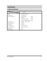
Page 4: ...20 230V 50HZ AC POWER CONSUMPTION MAXIMUM POWER 3200W MICROWAVE 1 500W GRILL HEATING ELEMENT 1450W CONVECTION HEATING ELEMENT 1700W OUTPUT POWER 90W 900W 10 LEVEL IEC 705 OPERATING FREQUENCY 2 450MHz MAGNETRON OM75PH 31 COOLING METHOD COOLING FAN MOTOR OUTSIDE DIMENSIONS 547 W x 339 H x 528 D NET WEIGHT 26 Kg SHIPPING WEIGHT 30 Kg ...

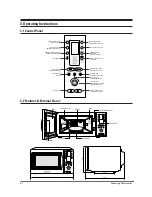
Page 5: ...NG WEIGHT SELECTION AND SERVING SELECTION START COOKING TIME ADJUSTMENT BUTTONS CONVECTION MODE TEMPERATURE SELECTION COMBINED MODE SELECTION MICROWAVE CONVECTION CLOCK SETTING AUTO DEFROST FEATURE SELECTION STANDING TIME SETTING STOP BUTTON Grill MW Grill 1min 1 Pizza 2 Oven Chips 3 Pie Quiche 3 Operating Instructions 3 1 Control Panel 3 2 Features External Views Door VentilationHoles Heater Ligh...

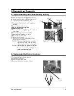
Page 6: ... screws from the back panel 8 Remove the assy noise filter 9 Take out the fan motor 10 Remove the oven lamp by pulling out from hole of air cover carefully NOTE1 When removing the magnetron make sure that its antenna does not hit any adjacent parts or it may be damaged NOTE2 When replacing the magnetron be sure to remount the magnetron gasket in the correct position and make sure the gasket is in ...

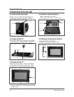
Page 7: ...ng the upper hinge and lower hinge Then remove the door assembly Insert flat screwdriver into the gap between Door A and Door C to remove Door C Be careful when handling Door C because it is fragile Following the procedure as shown in the figure insert and bend a thin metal plate between Door E and Door A until you hear the tick sound 1 Insertion depth of the thin metal plate should be 0 5mm or le...

Page 8: ...tch and power relay 3 When the above three switches operate properly check if any other part such as the control circuit board blower motor or high voltage transformer is defective 4 4 Replacement of Fuse 4 5 Replacement of Drive Motor Screw Drive Motor Cover Base Plate Thermo Switch Drive Motor 4 3 5 Reassembly Test After replacement of the defective component parts of the door reassemble it and ...

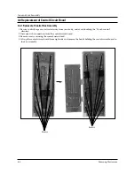
Page 9: ...ricity from your body and avoid touching the Touch control clrcuitry 2 Disconnect the connectors from the control circuit board 3 Remove screws securing the control circuit bord 4 Lift up the control circuit board from right side and remove the hooks holding the contol circuit board to the box assembly Disassembly and Reassembly Screws Screws ...

Page 10: ...inal and magnetron case should read open 1 The low voltage transformer is located on the control circuit board 2 Remove the low voltage transformer from the PCB Ass y and check continuity 3 Normal resistor reading is shown in the table PRECAUTION 1 High voltage is present at the high voltage terminals during any cook cycle 2 It is neither necessary nor advisable to attempt measurement of the high ...

Page 11: ... assembly adjust the Latch Body by moving it so that the oven door will not have any play in it Check for play in the door by pulling the door assembly Make sure that the latch keys move smoothly after adjustment is completed Completely tighten the screws holding the Latch Body to the oven assembly 3 Reconnect to Monitor switch and check the continuity of the monitor circuit and all latch switches...

Page 12: ...r glass vessel with water 2 Stir water in glass vessel with thermometer and record glass vessel s temperature T1 10 1 C 3 After moving the water into another glass vessel place it in the center of the cooking tray Set the oven to high power and operate for 48seconds exactly 1 5 seconds included as a holding time of magnetron oscillation 4 When heating is finished stir the water again with the ther...

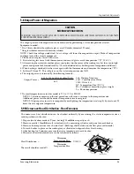
Page 13: ...enting device make a repair record for the measured values and keep the data 2 If the radiation leakage is more than 4 mW cm2 after determining that all parts are in good condition functioning properly and the identical parts are replaced as listed in this manual notift that fact to CENTRAL SERVICE CENTER 5 13 2 At least once a year have the microwave energy survey meter checked for accuracy by it...

Page 14: ...sing switch 3 Defective monitor switch NOTE1 4 Shorted HVCapacitor 5 Shorted HVTransformer NOTE2 NOTE 1 All of these switches must be replaced at the same time refer to adjustment instructions Check continuity of power relay contacts and if it has continuity replace power relay also NOTE 2 When HVTransformer is replaced check diode and magnetron also Oven does not accept 1 Key input is not in Sequ...

Page 15: ...d 1 Loose fan and fan motor Tighten screws of fan motor 2 Loose screws on H V Transformer Tighten screws of H V Transformer 3 Shorted H V Diode Replace H V Diode Turntable motor does not rotate 1 Open or loose wiring of turntable motor Check the wire of turntable motor 2 Defective turntable motor Replace turntable motor Oven stops operation during cooking 1 Open or loose wiring of primary Adjust d...

Page 16: ... M30 M70 M31 M32 M5 M39 M40 M41 M42 M43 M44 M45 M46 M50 M29 M51 M61 M63 M64 M65 M66 M67 M68 M72 M73 M52 M53 M54 M55 M56 M57 M58 M60 M48 M49 M75 M76 M74 M59 M4 M6 M7 M9 M8 M10 M11 M13 M14 M15 M17 M71 M18 M19 M20 M21 M22 M23 M24 M69 M26 M27 M28 M62 M16 M12 M33 M34 M35 M37 M38 M36 NC NO COM ...

Page 17: ... CMO CERAMIC 1 M18 DE61 30129A SUPPORTER PCB DASS T9N 2 C PCB M19 DE31 10080A MOTOR FAN AMM92 002AUEE 230V0 20A MIN255 1 M20 DE39 40606A WIRE HARNESS A 230V50HZ CE105K CE115K EUROPE 1 M21 4713 001046 LAMP INCANDESCENT 240V 104mA 25W ORG 25x62mm 1 M22 DE65 20025A CABLE CLAMP DAWS 2NB NYLON66 NTR WIRE SADD 1 M23 DE63 90065E CUSHION LAMP PUT FOAM T40 W10 L90 M6245 1 M24 DE01 00051A FILM LAMP T0 25 W1...

Page 18: ... M56 DE72 60035Q GUIDE AIR SECC T 0 6 W 240 L 242 5 RE 1 M57 DE39 40637A WIRE HARNESS B 230V50HZ CE115K 1 M58 DE39 40409A WIRE HARNESS E 230V50HZ M9G45 CTW 1 M59 DE65 20012A CORD CLAMP DALC 2 1 SILICON 1 TEMP W M60 ASSY CONTROL BOX 1 M61 ASSY DOOR 1 M62 DE63 90062A CUSHION RUBBER DOOR RUBBER CR T9 W30 L50 RE 1300 1 M63 DE74 20025C TRAY CONVECTION SPP T0 8 W12 L325 9 CE104CF 1 M64 DE74 20016A TRAY ...

Page 19: ...6 L397 CE 1 D 4 DE64 40286A DOOR SUB PC T2 0 W267 6 L402 6 100G BLK 1 D 5 DE92 50080E ASSY DOOR E MBG45 COATING SIL SELANT 1 D 6 DE64 40173A DOOR C PBT BLK 24G RE 1300 1 D 7 DE02 00082A TAPE DOUBLE FACE PET T0 4 W9 WHT SEIL SI 500HI 1 D 8 DE64 40175A DOOR KEY POM TC3005 BLK 13G RE 330 1 D 9 DE61 70041B SPRING KEY ES HSW3 PI0 7 D4 9 BLUING RE 7 1 D10 DE60 60008F PIN HINGE PI4 L15 NYLON 66 CE115K BL...

Page 20: ... DEFROST PC WHT 20G CE115K 1 C 5 DE66 20191A BUTTON MORE PC WHT 13G CE115K 1 C 6 DE66 20193A BUTTON CANCEL PC WHT 20G CE115K 1 C 7 DE67 40150A WINDOW DISPLAY ACRYL SMG 30G CE115K SAW 1 C 8 DE72 70185Z CONTROL PANEL PC CE325KF CE118KF 1 C 9 DE64 10132A KNOB PC WHT 10G CE115K 1 C10 RC 115K 00 ASSY PCB PARTS CE118KF AC230V50HZ 1 C11 DE93 30419X ASSY CONTROL BOX CE325KF WHITE CE118KF 1 C2 C7 C4 C5 C6 ...

Page 21: ...0098A ADIABATIC CASING T5 W245 L336 8 CE115K 1 6 DE61 50484A BRACKET HEATER STS430 T0 8 W27 2 L26 CE115K 1 7 DE47 70077A HEATER CONVECTION 230V 1680W 30 7 7 0 1 8 DE92 90487A ASSY COVER CASING CE115K 230V50HZ 1 9 DE62 10014A INSULATION TCO T2 0 W34 L26 YEL 1 10 DE47 20029A THERMOSTAT PW 2N 160 60 Y 23 8 250V 7 5A 1 11 DE31 90019A BLADE FAN SECC T0 6 1 12 DE31 10171A MOTOR CONVECTION SMC 105EA 230V...

Page 22: ...0082H SCREW A 2S 4X12 TOOTHED 2 B LATH DE60 10082H SCREW A 2S 4X12 TOOTHED 1 B WAVE DE60 10082H SCREW A 2S 4X12 TOOTHED 6 BASE P DE60 10082H SCREW A 2S 4X12 TOOTHED 1 BKT U DE60 10082H SCREW A 2S 4X12 TOOTHED 1 CN BOX DE60 10082H SCREW A 2S 4X12 TOOTHED 1 CV AIR DE60 10082H SCREW A 2S 4X12 TOOTHED 2 CV BAK DE60 10082H SCREW A 2S 4X12 TOOTHED 3 CV ADI DE60 10082H SCREW A 2S 4X12 TOOTHED 2 GR TCO DE...

Page 23: ...8 P C B Diagrams 8 1 P C B Diagrams Samsung Electronics 8 1 ...

Page 24: ... 000904 R CARBON 620OHM 5 1 8W AA TP 1 8X3 2MM 1 R18 P23 2001 001107 R CARBON S 220ohm 5 1 2W AA TP 2 4x6 4mm 3 R03 R04 R05 P24 2004 000195 R METAL 100Kohm 1 1 8W AA TP 1 8x3 2m 1 R12 P25 2004 001118 R METAL 5Kohm 1 1 4W AA TP 2 4x6 4mm 1 R11 P26 2202 000205 C CERAMIC MLC AXIAL 22pF 5 50V SL TP 1 9x3 5 2 C11 C12 P27 2202 000780 C CERAMIC MLC AXIAL 100nF 80 20 50V Y5V TP 3 5x1 5 C08 C09 C10 C13 C14...

Page 25: ... COM 0V GRILL RELAY RED YEL YEL WHT WHT BLU BLU CONV HEATER CONV T C O CONV RELAY FM H V T H V D H V C MONITER FUSE 1 6A H V FUSE 0 8A 1mH L V T PRIMARY LATCH SWITCH DOOR SENSING SWITCH MONITOR SWITCH KEY BOARD CONDITION OF OVEN DOOR IS OPENED BRN BROWN WHT WHITE RED RED Y G YELLOW GREEN BLU BLUE ORG ORANGE YEL YELLOW PNK PINK COOK OFF WIRING COLOR A S S Y M A I N P C B Thermistor Sensor Thermisto...

Reviews: