Schematic Diagrams
◆
Block Identification of Main PCB
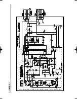
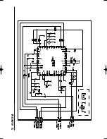
1 S.M.P.S.-1
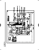
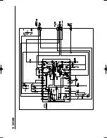
2 S.M.P.S.-2
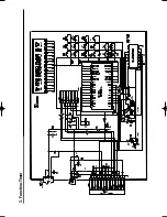
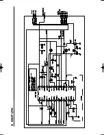
3 Function-Timer
◆
VCR Main PCB
4 Volume
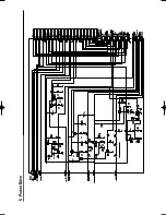
5 Power Drive
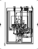
6 Logic
7 A/V
8 Hi-Fi
9 AM/FM Receiver
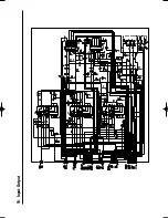
10 Input-Output
11 TM
12 A2/NICAM
13 SECAM
14 OSD/VPS/PDC
◆
DVD Main PCB
15 DVD Micom
16 DVD DVI (CHT-600 Only)
17 DVD Servo
18 DVD Audio/Video Interface
19 Digital Amp
For schematic Diagram
- Resistors are in ohms, 1/8W unless otherwise noted.
Note
Special note :
Most semiconductor devices are electrostatically sensitive and therefore require the special handling
techniques described under the “electrostatically sensitive (ES) devices” section of this service manual.
Note :
Do not use the part number shown on this drawing for ordering. The correct part number is shown in the parts
list (may be slightly different or amended since this drawing was prepared).
Important safety notices :
Components identified with the mark have the special characteristics for safety. When replacing any of
these components.
Use only the same type.
00404A CHT-500/XST-GB4 7/5/04 6:40 PM Page 75
Summary of Contents for CHT-500
Page 77: ...1 S M P S 1 ...
Page 78: ...2 S M P S 2 ...
Page 79: ...3 Function Timer ...
Page 80: ...4 Volume ...
Page 81: ...5 Power Drive ...
Page 82: ...6 Logic ...
Page 83: ...7 A V ...
Page 84: ...8 Hi Fi ...
Page 85: ...9 AM FM Receiver ...
Page 86: ...10 Input Output ...
Page 87: ...11 TM ...
Page 88: ...12 A2 NICAM ...
Page 89: ...13 SECAM ...
Page 90: ...14 OSD VPS PDC ...
Page 91: ...15 DVD Micom ...
Page 92: ...16 DVD DVI CHT 600 Only ...
Page 93: ...17 DVD Servo ...
Page 94: ...18 DVD Audio Video Interface ...
Page 95: ...19 Digital Amp ...
Page 96: ...THIS APPLIANCE IS DISTRIBUTED BY www samsungvcr com AK68 00404A ELECTRONICS ...

