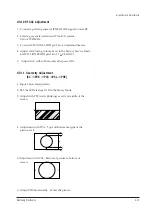
4-3-11 Geometry Adjustment
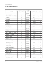
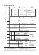
(SC -> PVS -> PVA ->PSL -> PHS)
1. Input a Lion Head pattern.
2. SET the SC Data steps 10~12 in the Factory Mode.
3. Adjust with PVS (starts blinking) exactly at middle of the
screen.
4. Adjustment with PVA : Top and Bottom margins of the
picture are 4.
5. Adjustment with PSL : Bottom of picture to bottom of
screen.
6. Adjust PHS horizontally. Center the picture.
4-11
Alignment and Adjustments
Samsung Electronics
4
4
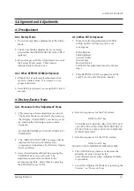
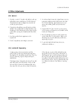
4-3-10 RF AGC Adjustment
1. Connect a pattern generator (PM5418) RF signal to tuner RF.
2. Select a gray scale pattern and PAL-B/G system.
Set to 479.25MHz.
3. Connect IC201 (ONECHIP) pin 53 to a digital multimeter.
4. Adjust AGC (using volume keys) in the Factory Service Mode.
Set IC201 (ONECHIP) pin 54 to 3.7 + 0.05v(DC).
5. Adjust AGC within 20 seconds after power ON.
Summary of Contents for CK564BZR1X/BWT
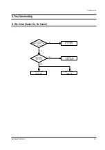
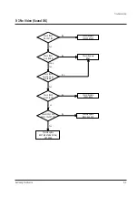
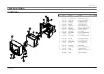
Page 2: ...ELECTRONICS Samsung Electronics Co Ltd MAY 1998 Printed in Korea 3SCT57B 6604 ...
Page 13: ...3 4 Samsung Electronics MEMO MEMO ...
Page 25: ...4 12 Samsung Electronics MEMO MEMO ...
Page 47: ...Schematic Diagrams 11 1 Samsung Electronics 11 Schematic Diagrams 11 1 MAIN POWER ...
Page 48: ...Schematic Diagrams 11 2 Samsung Electronics 11 2 MAIN CHROMA ...
Page 49: ...Schematic Diagrams 11 3 Samsung Electronics 11 3 MAIN AUDIO ...
Page 50: ...Schematic Diagrams 11 4 Samsung Electronics 11 4 MAIN U COM ...
Page 51: ...Schematic Diagrams 11 5 Samsung Electronics 11 5 MAIN CRT ...
Page 52: ...Schematic Diagrams 11 6 Samsung Electronics 11 6 STEREO SIF ...
Page 53: ...Schematic Diagrams 11 7 Samsung Electronics 11 7 MAIN NICAM ...
Page 54: ...Schematic Diagrams 11 8 Samsung Electronics 11 8 PIP TTX ...
Page 55: ...Schematic Diagrams 11 9 Samsung Electronics 11 9 TTX OPTION ...
Page 56: ...Schematic Diagrams 11 10 Samsung Electronics 11 10 PCB A V ...


