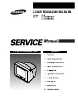


COLOR TELEVISION RECEIVER
Chassis :
K15D
Model :
CL17M6MQFX/XAP
CL17M6MQFX/RCL
COLOR TELEVISION RECEIVER
CONTENTS
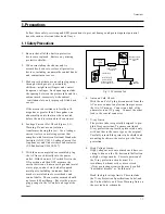
Precautions
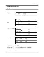
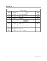
Specifications and IC Data
Disassembly and Reassembly
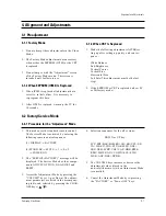
Alignment and Adjustment
Troubleshooting
Exploded View and Parts List
Electrical Parts List
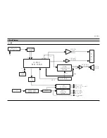
Block Diagram
Wiring Diagram
Schematic Diagrams
1.
2.
3.
4.
5.
6.
7.
8.
9.
10.
Summary of Contents for CL17M6MQFX/RCL
Page 2: ...ELECTRONICS Samsung Electronics Co Ltd MAY 2003 Printed in Korea AA82 00654A ...
Page 6: ...2 4 MEMO ...
Page 23: ...3 4 Samsung Electronics MEMO ...
Page 33: ...7 10 Samsung Electronics MEMO ...
Page 39: ...Schematic Diagrams 10 4 Samsung Electronics 10 4 MAIN 4 4 ...
Page 45: ...9 2 MEMO ...


