background image

4-3-9  RF AGC Adjustment

Set the AGC data to 33 (Factory Mode).

4-3-10 Sub-Color Adjustment

Set            data to       (Factory Mode).

4-3-11  Geometry Adjustment

SC 

VS

VA

VSL

HS

1.  Input a lion head pattern.

2.  Set the SC (S-Correction) as 29 and VS(Vertical

Shift) 31 so that the lion head circle becomes
oval.

3.  Adjust with VA (Vertical Amplitude) so that

the top  margin of the picture is 4.

Fig. 4-7

4.  Adjust with VSL (Vertical-Slope) so that the

bottom margin of the picture is 4.

Fig. 4-8

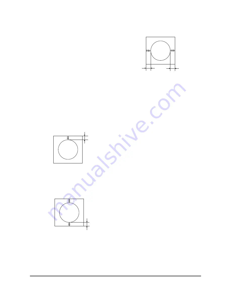
5.  Adjust with HS (Horizontal Shift) so that the

lion-head pattern and CRT centers are aligned.

Fig. 4-9

6.  Adjust EWID (EW Width) so that the  left and

right margins of the picture are 5.

7. Input a cross-hatch pattern.

Alignment and Adjustments

Samsung Electronics

4-9

4

5

5

4

NSR

10

Summary of Contents for CL29K5MQKX/XAP

Page 1: ... COLOR TELEVISION RECEIVER CONTENTS Precautions Specifications and IC Data Disassembly and Reassembly Alignment and Adjustment Troubleshooting Exploded View and Parts List Electrical Parts List Block Diagram Wiring Diagram Schematic Diagrams 1 2 3 4 5 6 7 8 9 10 ...

Page 2: ...ELECTRONICS Samsung Electronics Co Ltd MAY 2003 Printed in Korea AA82 00622A ...

Page 3: ...dle brackets metal cabinets screwheads and control shafts The current measured should not exceed 0 5 milliamp Reverse the power plug prongs in the AC outlet and repeat the test Fig 1 1 AC Leakage Test 6 Antenna Cold Check With the unit s AC plug disconnected from the AC source connect an electrical jumper across the two AC prongs Connect one lead of the ohmmeter to an AC prong Connect the other le...

Page 4: ...t appear to have overheated or that are otherwise damaged should be replaced with parts that meet the original specifications Always determine the cause of damage or overheat ing and correct any potential hazards 15 Observe the original lead dress especially near the following areas Antenna wiring sharp edges and especially the AC and high voltage power supplies Always inspect for pinched out of p...

Page 5: ...g and accessible conductive parts examples metal panels input terminals and earphone jacks 6 Insulation Checking Procedure Disconnect the power cord from the AC source and turn the power switch ON Connect an insulation resistance meter 500V to the blades of the AC plug The insulation resistance between each blade of the AC plug and accessible conductive parts see above should be greater than 1 meg...

Page 6: ...n anti static solder removal device Many solder removal devices are not rated as anti static these can accumulate sufficient electrical charge to damage ESDs 7 Do not remove a replacement ESD from its protective package until you are ready to install it Most replacement ESDs are packaged with leads that are electrically shorted together by conductive foam aluminum foil or other conductive material...

Page 7: ... Requirements Antenna Input Impedance Speaker Impedance NTSC NTSC 2 13 14 69 45 75 41 25 42 18 System Band VHF UHF 1 125 CABLE SYSTEM IF Carrier Frequency Picture IF Carrier Sound IF Carrier Color Sub Carrier MODEL TXM2792FX 29 Inch AC 120V 60Hz VHF UHF Telescopic dipole antenna 75 ohm unbalanced type 8 ohm 15W 15W Dual Type SYSTEM NTSC ONLY A68QCP891X100 29Inch Flat 380MG ...

Page 8: ...D VERTICAL OUTPUT LA7845 TDA7297 IC301 IC602 SOUND AMP 15W x 2CH IC801S KA5Q1265R POWER IC STR IC802 KA7632 CUSTOM REGULATOR 5V 8V 3 3V IC101 LA7510 IF DETECTOR IC TEMIC IC601 ICP01 ICW01 ICG01 MSP 3425G B8 Sound Processor VIPER12AD1P PWM CONTROCER IC NJM2235D VIDEO Swiching IC 4558 OP AMP IC Micronas Sanyo TDA6108QJF RGB DRIVE AMP M24C08 EEPROM TCET1108 LTV817B PHOTO COUPLER Specification Descrip...

Page 9: ...DIODE SPM464A Pin 64 MSP3425G Pin 52 LM393 Pin 8 VIPER12ADIP Pin 8 M24C08 Pin 8 4558 Pin 8 NJM2235D Pin 8 IC TRANSISTOR LA7845 Pin 7 TDA6108Q Pin 9 KA7632 Pin 10 TRANSISTOR TRANSISTOR KSD5703 KSA614 B C E E B C KSC815 Y KSA539 Y SAW FILTER E C B KSC2331 Y 1 1 1 M3953M M9370M Fig 2 1 Semiconductor Base Diagrams ...

Page 10: ...2 4 MEMO ...

Page 11: ...reassembly Samsung Electronics 3 1 3 Disassembly and Reassembly 3 1 Back Cover Removal 1 After removing the screws press the tension rib and pull the cabinet backwards 2 To reassemble press the tension rib see diagram ...

Page 12: ...cket board from the CRT neck 2 Remove the Anode Cap from the CRT 3 Remove the main board by pulling it with both hands Warning The FBT is charged with high voltage Before removing the Anode Cap discharge the voltage through one of the heat sinks on the main board 1 Remove the speaker by pressing the tension rib ...

Page 13: ...RT to the front cabi net Lift the CRT 3 Caution Because of the high vacuum and large surface area of the picture tube be careful while handling it 1 Always lift the picture tube by grasping it firmly around the faceplate 2 Never lift the tube by its neck 3 Do not scratch the picture tube or apply excessive pressure Fractures of the glass may cause an implosion ...

Page 14: ...3 4 Samsung Electronics MEMO ...

Page 15: ...or CRT is replaced and set SC as 30 factory mode 4 2 Factory Service Mode 4 2 1 Procedure for the Adjustment Mode 1 This mode uses the standard remote control The Service Mode is activated by entering the following remote control sequence 1 DISPLAY FACTORY 2 STAND BY MUTE 1 8 2 POWER ON 2 The SERVICE FACTORY message will be displayed The Service Mode has four compo nents ADJUST OPTION G2 ADJUST an...

Page 16: ...l or 0 23 SCBT Screen Brighrtness 0 63 VOL Vol ume pre s et t i ng 0 63 0 63 0 63 0 63 0 63 0 63 CAP Caption Position Melody Volume Ratio Pre overshoot Ratio Pre overshoot IF AGC Speed Offset IF Demodulator Soft Clipping Level Peak White Limitting Color Matrix Automatic Gain Control Horizontal Parallelogram Horizontal Bow EW Width MVOL RP00 RP01 AGCS OMD SCL PWL MUS AGC HPAR HBOW EWID 13 9 32 32 2...

Page 17: ...ion sens Sub Sharpness Amplitude of SVM Output Delay of RGB to VM Output Vertical Zoom EW Trapezium EW Lower Coner EW Upper Coner EW Parabola 0 1 0 1 0 3 0 3 EPAR ELCN EUCN ETRP VZ SVM VMA SSP PSNS DNSR DSBT DCDL DBLR DBLB 32 12 12 12 48 0 3 5 1 5 4 10 32 32 0 ADJ ADJ ADJ ADJ FIX FIX FIX FIX FIX FIX FIX FIX FIX FIX FIX 33 34 35 36 37 38 39 40 41 42 43 44 45 46 47 O NO SD F UN CTI ON R AN GE I N I ...

Page 18: ...CREEN V CHIP AV OPTION TILT DEMO EXT COMB V Guard SETTING CT N EN SP FR OFF NOR ZOOM OFF ON ENGLISH OFF OFF ON AV1 AV2 S V DVD ON OFF OFF ON Language Video Mute On Off changing the channel Picture Size Option Master S w Option Audio Mute On Off without signal Inital Language agter Factory Reset Hotel mode On Off Bule Screen On Off without signal V CHIP ON OFF U S A AV S V DVD TILT ON OFF DEMO ON O...

Page 19: ... on Make sure that the power cord is disconnected before replacing any parts 8 To protect against shock hazard use an isola tion transformer 4 3 2 Automatic Degaussing A degaussing coil is mounted around the pic ture tube so that external degaussing after moving the TV should be unnecessary But the receiver must be properly degaussed upon installation The degaussing coil operates for about 1 sec o...

Page 20: ... Adjustment Screen Adjustment 1 Input a Toshiba pattern 2 Go to service mode and select G2 Adjust 3 Adjust bottom VR of FBT to display SCREEN ADJUST OK 4 Use the Menu or Mute key to complete G2 adjustment 4 3 6 Purity Adjustment 1 Warm up the receiver for at least 20 minutes 2 Plug in the CRT deflection yoke and tighten the clamp screw 3 Plug the convergence yoke into the CRT and set in as shown i...

Page 21: ... Adjustment 31m m Vertical Green Belt Fig 4 4 1 2 a Set up 1 Warm up the TV for at least 30 minutes in the Aging Mode OSD White This mode is dis played by entering the following sequence DISPLAY FACTORY FACTORY 2 Input a Toshiba pattern b Low Light Adjustment 1 Set SBT to 1 5 fL in the Factory Service Mode with using CA100 See Fig 4 4 2 Adjust RG BG so that the levels are suitable to each local ar...

Page 22: ...and the blue vertical lines in the center area of the screen 5 Turn the both tabs at the same time keeping the angle constant and superimpose the red and blue horizontal line in the center of the screen 6 Adjust the two tab pairs of the 6 pole magnets to superimpose the red and blue line onto the green Changing the angle affects the vertical lines and rotating both magnets affects the horizontal l...

Page 23: ...ircle becomes oval 3 Adjust with VA Vertical Amplitude so that the top margin of the picture is 4 Fig 4 7 4 Adjust with VSL Vertical Slope so that the bottom margin of the picture is 4 Fig 4 8 5 Adjust with HS Horizontal Shift so that the lion head pattern and CRT centers are aligned Fig 4 9 6 Adjust EWID EW Width so that the left and right margins of the picture are 5 7 Input a cross hatch patter...

Page 24: ... Geometry Alignment and Adjustments 4 10 Samsung Electronics 3 EWID EW Width 7 ETRP EW Trapezivm 2 HBOW Horizontal Bow 1 HPAR Horizontal Parallelogram 5 EUCN EW Upper Coner 6 ELCN EW Lower Coner 4 EPAR EW Parabola ...

Page 25: ...Alignment and Adjustments Samsung Electronics 4 11 ...

Page 26: ...MEMO 4 12 Samsung Electronics ...

Page 27: ...al Abnormal Abnormal Abnormal Counect the Power code Check the Power LED Check the X tal SDA SCL port of IC201S Check the 33 Pin H Drive of IC201S Check the 130V A Line Check the 3 3V A 8V A Line of IC201S Check Replace IC802 Replace IC201 S Check the FBT D808 Check the 12 5V A Line Check the FD802S IC801S or AC Fuse Check Replace Q401 ...

Page 28: ...l Check RK GK BK Signal Check R G B Signal into CRT PCB Check the resistance of R519 Check IC201S Pin50 IK V GUARD Check IC501 B 180V B Check the Voltage of heater Check CRT and FBT Check Replace D407 FBT Check IC301 B Volt Replace R519 D406 R414 D405 R413 Check Replace IC301 Check Replace Check CRT and FBT Check Replace IC201S Check Replace R418 R522 R523 Check IC201S Pin 51 52 53 R G B ...

Page 29: ...ckthe signal Output from CN602 CN603 Check Speaker and Wire Check Replace IC601 Check B Line 5V B 8V B Check IC101 TUNER See No Power Replace IC602 Replace FD801S D805 Check IC602 Pin4 12 Check IC601 Pin47 SIF Check IC601 B Check IC602 B Check FD801S D805 Abnormal Abnormal Abnormal Abnormal Abnormal Abnormal ...

Page 30: ...lectronics Troubleshooting 5 4 Horizontal Lines Appear or Screen Normal Normal Abnormal Abnormal Check R413 R414 D405 D406 Check IC201S Check IC201S Pin 21 22 VDN VDP Check IC301 B 16V C 13 5V C Check Replace IC301 ...

Page 31: ...AA64 02632A WINDOW RMC LED 29K5 PC CLR 1 WR 1 11 6003 001026 SCREW TAPTITE RH B M4 L15 ZPC BLK SWR 1 WR CF 1 12 AA64 02635A KNOB CONTROL 29K5 ABS HB G3676 SVM 3012 1 KC 1 13 6003 001026 SCREW TAPTITE RH B M4 L15 ZPC BLK SWR 1 KC CF 1 14 AA91 00507A ASSY HOLDER SPK 8OHM 15W ASSY HOLD 1 AHS 1 15 6006 001095 SCREW ASS Y TAPT WP BH M4 L12 ZPC YEL 4 SPK CF 2 AA03 00273A CRT COLOR A68QCP891X100 380MG 1 ...

Page 32: ...ZIP 15P DUA 4 6003 000333 SCREW TAPTITE RH 2S M3 L10 ZPC YEL SW 4 AA62 30182E HEAT SINK ES A6063 EXTR WHT 40 3 IC301 AA96 50406G ASSY H S POWER AA62 30180K K57A 4 1204 001807 IC VERTICAL PROCESSO LA7841 SIP 7P 708MI 4 6003 000333 SCREW TAPTITE RH 2S M3 L10 ZPC YEL SW 4 AA62 30180K HEATSINK ES A6063EXTR WHT 50 13 4 0205 000129 GREASE SILICON SC102 JAPAN 3 D805 BP96 00020F ASSY HEAT SINK P H S TR SC...

Page 33: ...2001 000281 R CARBON 100OHM 5 1 8W AA TP 4 R274 2001 000281 R CARBON 100OHM 5 1 8W AA TP 4 R275 2001 000281 R CARBON 100OHM 5 1 8W AA TP 4 R276 2001 000281 R CARBON 100OHM 5 1 8W AA TP 4 R277 2001 000281 R CARBON 100OHM 5 1 8W AA TP 4 R288 2001 000281 R CARBON 100OHM 5 1 8W AA TP 4 R296 2001 000281 R CARBON 100OHM 5 1 8W AA TP 4 R605 2001 000281 R CARBON 100OHM 5 1 8W AA TP 4 R606 2001 000281 R CA...

Page 34: ...1 000599 C CERAMIC DISC 560PF 10 500V 4 C816 2201 000599 C CERAMIC DISC 560PF 10 500V 4 C405 2201 000639 C CERAMIC DISC 680PF 10 2KV Y5P 5MM T 4 CW04 2201 000982 C CERAMIC DISC 10NF 80 20 50 4 C820 2201 000991 C CERAMIC HIC CK45 T B2KV561 K 4 C110 2202 000127 C CERAMIC MLC AXIAL 10NF 80 2 4 C120 2202 000127 C CERAMIC MLC AXIAL 10NF 80 2 4 C603 2202 000286 C CERAMIC MLC AXIAL 56PF 5 50 4 C629 2202 ...

Page 35: ...802 3301 000287 CORE FERRITEBEAD AA 3 5X1 0X6 4 L804 3301 000287 CORE FERRITEBEAD AA 3 5X1 0X6 4 L806 3301 000287 CORE FERRITEBEAD AA 3 5X1 0X6 4 L303 3301 000287 CORE FERRITEBEAD AA 3 5X1 0X6 4 L809 3301 001223 CORE FERRITE BEAD AB 3 5X5X0 8MM TP 4 FD802S 3601 001163 FUSE AXIAL LEAD 125V 7A EPOXY 2 4X7 1M 4 FD801S 3601 001228 FUSE AXIAL LEAD 125V 10A FAST ACTING EPO 4 F801A 3602 000114 FUSE HOLDE...

Page 36: ...EY301 6042 000002 EYELET IDI 5 OD2 L3 1 SN BSS3 E EH 4 EY302 6042 000002 EYELET IDI 5 OD2 L3 1 SN BSS3 E EH 4 EY303 6042 000002 EYELET IDI 5 OD2 L3 1 SN BSS3 E EH 4 EY304 6042 000002 EYELET IDI 5 OD2 L3 1 SN BSS3 E EH 4 EY401 6042 000002 EYELET IDI 5 OD2 L3 1 SN BSS3 E EH 4 EY402 6042 000002 EYELET IDI 5 OD2 L3 1 SN BSS3 E EH 4 EY403 6042 000002 EYELET IDI 5 OD2 L3 1 SN BSS3 E EH 4 EY404 6042 0000...

Page 37: ...00mW D 3 DZG501 0403 001328 DIODE ZENER MTZJ22A 20 15 21 20V 500mW D 3 QG01 0501 000283 TRANSISTOR KSA539 Y TAPG YTAM 3 QF03 0501 000369 TRANSISTOR KSC2331 Y TAPG 3 QF01 0501 000389 TRANSISTOR KSC815 Y TAPG YTAM 3 QF02 0501 000389 TRANSISTOR KSC815 Y TAPG YTAM 3 RF09 2001 000221 R CARBON 1 2KOHM 5 1 8W AA TP 3 RF12 2001 000221 R CARBON 1 2KOHM 5 1 8W AA TP 3 RF10 2001 000241 R CARBON 1 5KOHM 5 1 8...

Page 38: ...B LEAD CONNECTOR ASSY YFH800 01 500MM 1P 3 CN501A 3711 002648 POST HEADER 67094 009 AUTO 3 CN502A 3711 002645 POST HEADER 67094 006 AUTO 3 CNG01 3711 002643 POST HEADER YW025 04 AUTO 3 CNF01 3711 002642 POST HEADER 67094 003 AUTO 3 QG02 0502 000244 TR POWER KSA940 PNP 150V 150 3 QG03 0502 001007 TR POWER KSC2073 H2 NPN 150V 1 3 BAND AA63 10002A BAND TIE NYLON66V2 L100 NTR 3 C516 2301 000213 C FILM...

Page 39: ...A63 60004L SPACER GUM CRT NTR RUBBER BLK T3 2 INL CRT AA64 03072A INLAY COVER PS SHEET 50X30 T 1 0 ASSY ACCESSORY 1 A ACCS AA92 07703E ASSY ACCESSORY CL29K5MQKX XAP K57A 2 AC TAPE 0203 001279 TAPE OPP MASKING 232 T0 14 W15 L50000 Y 2 RMT AA59 00302F REMOCON TM58 SSM174PT 41 SS L GRAY MBR 2 I B AA68 02838A MANUAL USERS K57A SPA W P100 G 2 I B2 AA68 02839A MANUAL USERS K57A ENG W P100 G 2 C WARR AA6...

Page 40: ...UND AMP TDA7297S 15W2CH CRT DRI VE TDA6108JF VMC C2344 A1011 KEY CONTROL UOC Plus I C TDA 9592 TUNER Monitor out AV 2 i nput AV 1 i nput FBT FUH 29A001B Rela y Bri d ge Di ode Ma i n Tr ans Swit ch i ng I C STR KA5Q1265R REGULATOR I C KA7632 AUDIO SIGNAL PROCESSING MSP3425G VERTICAL LA7845 VI F SAW EEPROM X24C08P H OUT TR D5703 S Vi deo Y Pb Pr SI F SAW RMC ...

Page 41: ... IN R IN L OUT R OUT V IN GND V OUT GND 1 2 5 6 7 8 9 3 4 GND SENSE TILT GND SVM OUT GND G OUT B OUT R OUT CN501 CN701 1 2 5 6 3 4 HEATER B 16 5V B 13 5V N C GND B 210V CN502 1 2 5 6 3 4 GND SC OUT GND 7 SY OUT GND SY IN SC IN CN702 CN902 1 2 3 4 IR TI 5V GND CN901 1 2 3 GND KI KZ POWER CORD ...

Page 42: ...9 2 MEMO ...

Page 43: ...TP23 TP22 TP21 TP19 TP18 TP16 TP17 TP15 TP13 TP14 Schematic Diagrams 10 1 Samsung Electronics 10 Schematic Diagrams 10 1 MAIN 1 3 TP13 TP14 TP16 TP17 TP19 TP21 TP23 TP15 TP18 TP22 ...

Page 44: ...Schematic Diagrams 10 2 Samsung Electronics 10 2 MAIN 2 3 TP01 TP02 TP03 TP12 TP04 TP10 TP7 TP05 TP06 TP08 TP02 TP04 TP06 TP08 TP12 TP01 TP03 TP05 TP07 TP10 ...

Page 45: ...Schematic Diagrams 10 3 Samsung Electronics 10 3 MAIN 3 3 TP24 TP24 ...

Page 46: ...Schematic Diagrams 10 4 Samsung Electronics 10 4 CRT ...

Reviews: