
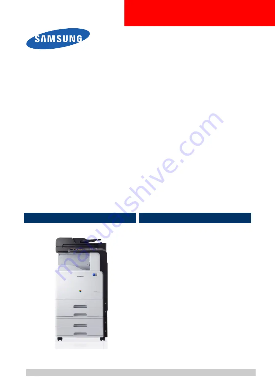
A3 Color Copier
CLX-9201/9251/9301 series
CLX-9201ND/NA,
CLX-9251ND/NA, CLX-9301NA
(Ver 3.29)
SERVICE
MANUAL
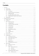
A3 Color Copier
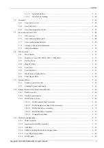
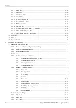
Contents
2. Product Specifications and Description
Refer to the service manual in the GSPN (see the rear cover) for more information.


