background image

MICROWAVE OVEN

SERVICE

Manual

MICROWAVE OVEN

CONTENTS

1. Precaution

2. Specifications

3. Operating Instructions

4. Disassembly and Reassembly

5. 

Alignment and


Adjustments

6. T

roubleshooting

7. Exploded 

V

iews and Parts List

8. Schematic Diagrams

9. W

iring Diagram & 


    Operating Sequence

CM1629

Version : 0001, 0002

SEF

Summary of Contents for CM1629

Page 1: ...ENTS 1 Precaution 2 Specifications 3 Operating Instructions 4 Disassembly and Reassembly 5 Alignment and Adjustments 6 Troubleshooting 7 Exploded Views and Parts List 8 Schematic Diagrams 9 Wiring Diagram Operating Sequence CM1629 Version 0001 0002 SEF ...

Page 2: ...ction within the microwave generating compartments check the magnetron wave guide or transmission line and cavity for proper alignment integrity and connections d Any defective or misadjusted components in the interlock monitor door seal and microwave generation and transmission systems shall be repaired replaced or adjusted by procedures described in this manual before the oven is released to the...

Page 3: ...sing switch and power relay as well as the Interlock Monitor Switch The correct adjustment of these switches is described else where in this manual Make sure that the fuse has the correct rating for the particular model being repaired 13 Design Alteration Warning Use exact replacement parts only i e only those that are specified in the drawings and parts lists of this manual This is especially impo...

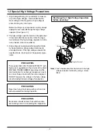
Page 4: ... the high voltage exceeds the specified limits check each of the special compo nents PRECAUTION There exists HIGH VOLTAGE ELECTRICITY with high current capabilities in the circuits of the HIGH VOLTAGE TRANSFORMER secondary and fila ment terminals It is extremely dangerous to work on or near these circuits with the oven energized DO NOT measure the voltage in the high voltage circuit including filamen...

Page 5: ...TPUT POWER OPERATING FREQUENCY MAGNETRON COOLING METHOD OUTSIDE DIMENSIONS NET WEIGHT SHIPPING WEIGHT Max 25min 230V 50Hz AC MICROWAVE 3 200W 1 600W ICE 705 2 450MHz OM75P 20 ESS VENTILATION MOTOR 464 W x 368 H x 557 D 32 Kg 34 5 Kg 2 1 Table of Specifications ...

Page 6: ... TRAY AIR FILTER 3 1 Control Panel 10 1 2 3 5 6 7 8 9 4 P 1 2 3 4 5 6 7 8 9 0 20sec 1 DISPLAY 2 PROGRAM PAD 3 PROGRAM LOCK PAD 4 NUMBER PADS TIME MEMORY PROGRAMMING 5 POWER LEVEL SELECTOR PAD 6 DEFROST SELECTOR PAD 7 DOUBLE QUANTITY PAD 8 20sec PAD ONE TOUCH COOK PAD 9 STOP CANCEL PAD 10 START BUTTON 514 1000 368 444 10 464 486 530 43 26 557 3 2 Features External Views ...

Page 7: ...s and all heating will stop The oven lamp will go off For1min thedisplay shows 0 and the cooling fan will keep working in order to cool down the interior parts During the time the fan will not stop even when you open the door 1 min later it will stop Food may be removed from oven whilst the fan is still running 4 Open the door and take the food out Close the door The oven lamp will go off Whilst i...

Page 8: ...R pads will not operate or respond when you press a cooking time exceeding the maximum value It is not possible to set a cooking time for longer than the maximum time allowed on the chosen program It is advisable to press CANCEL and to enter a new power level and cooking time 3 Repeat steps 1 and 2 for II or III stage memory programming 4 Press button Result The oven lamp and cooling fan will be t...

Page 9: ...isable to press CANCEL and enter a new defrost level and time Repeat Feature You can repeat the previous cooking setting regardless of manual or automatic memory heating by pressing the START button The oven starts with exactly the same heating time and power level that were used in the last operation NOTE Repeat feature does not support for 20sec pad The repeat feature will be cancelled once the ...

Page 10: ...title Power Levels and Time Variations The NUMBER pads will not operate or respond when you press a cooking time exceeding the maximum value It is not possible to set a cooking time for longer than the maximum time allowed on the chosen program It is advisable to press CANCEL and to enter a new power level and cooking time 5 Hold down PROGRAM LOCK and then press PROGRAM pad Hold together for 2 sec...

Page 11: ... exceeding the maximum value It is not possible to set a cooking time for longer than the maximum time allowed on the chosen program It is advisable to press CANCEL and to enter a new power level and cooking time 5 Repeat steps 3 and 4 for II or III stage memory programming 6 Hold down PROGRAM LOCK and then press PROGRAM pad Hold together for 2 sec once again Result PROG indicator and memory numbe...

Page 12: ...t any time so that you can Check the food Turn the food over or stir it Leave it to stand To stop the cooking Temporarily Open the door or press pad once Result Cooking stops To resume cooking close the door and press again Completely Press the pad twice Result The cooking settings are cancelled If you want to cancel any cooking settings before starting cooking simply press CANCEL pad once Power L...

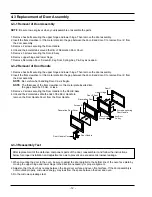
Page 13: ...magnetron by using a box wrench 6 Take out the magnetron very carefully NOTE 1 When removing the magnetron make sure that its antenna does not hit any adjacent parts or it may be damaged NOTE 2 When replacing the magnetron be sure to remount the magnetron gasket in the cor rect position and make sure the gasket is in good condition See page 19 for adjustment instructions Duct MGT L Nut Flange Duct...

Page 14: ...le NOTE The thickness of the flat screwdriver or thin metal plate inserted into the gap should be 0 5mm or less 3 Remove 2 screws securing the Door Handle to the Door E Assy 4 Unbend the 2 metal tabs at both ends of the Door Handle to remove the Door Handle Cover from the Door Handle 4 3 3 Reassembly Test 1 When mounting the door to the oven be sure to adjust the door parallel to the bottom line of...

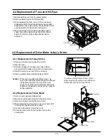
Page 15: ...h hands and pull them in and down 4 Take the ceiling cover out of the oven cavity 5 Remove plastic clips securing the Ass y Stirrer Caution When removing the Assy Stirrer Cover be sure to be extremely careful about the exposed inside components on the top of the oven cavity If any of them are deformed abnormal symptom can happen such as arcing or sparks during operation 4 5 2 Replacement of Drive ...

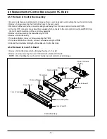
Page 16: ...e control box assembly 5 Remove a screw securing the tapped taping to PCB1 6 Remove Control Box Ass y 7 To replace Digitron remove 2 screws securing the PCB4 8 To replace Start Button Circuitry remove 3 screws securing the PCB3 9 Unbend the metal tabs holding the Panel Base to Control Box body 4 6 2 Removal of main P C Board 1 Remove Control Box Assembly by following the steps 1 5 at left 2 Remove...

Page 17: ...ray by inserting a thin metal tool into the gap between the oven wall and the tray silicon cover 3 Insert the new tray by tilting it across the oven cavity 4 Firstly fix the front part refers to the place where the silicon cover is thinner than the other 3 edges and then place the backward part carefully and firmly NOTE Be careful when you handle the tray since it is fragile 4 8 Replacement of Tray ...

Page 18: ...he post carefully Note Spacer pins are not detachable from the Air Filter Plastic Spacer Pins NOTE It is not necessary to remove Magnetron in order to remove HVC 1 Remove the outer panel and back cover 2 Discharge the high voltage capacitor 3 Remove HVT wire and H V Fuse 4 Remove screws securing HVC bracket 4 11 Replacement of High Voltage Capacitor H V Capacitor ...

Page 19: ...lament terminals should indicate one ohm or less 3 A continuity check between each filament terminal and magnetron case should read open 1 The low voltage transformer is located on the base plate 2 Remove the low voltage transformer from the base plate and check continuity 3 Normal resistor reading is shown in the table Terminal Resistance Wire 1 2 input 3 4 output 20V 5 6 output 3 2V Approx 296Ω A...

Page 20: ...eck for play in the door by pulling the door assembly Make sure that the latch keys move smoothly after adjustment is completed Completely tighten the screws holding the Latch Body to the oven assembly 3 Reconnect to Monitor switch and check the continu ity of the monitor circuit and all latch switches again by following the components test procedures 4 Confirm that the gap between the switch housi...

Page 21: ...t To Room temperature 26 7 Normal temperature rise for this model is 9 C to 11 C at HIGH NOTE 1 Variations or errors in the test procedure will cause a variance in the temperature rise Additional power test should be made if temperature rise is marginal NOTE 2 Output power in watts is computed by multiplying the temperature rise step 5 by a factor of 90 times of centi grade temperature CAUTION MIC...

Page 22: ...neous readings may result 5 Measured leakage must be less than 4mW cm2 after repair or adjustment 5 10 2 Note on Measurement 1 Do not exceed the limited scale 2 The test probe must be held on the grip of the handle otherwise a false reading may result when the opera tor s hand is between the handle and the probe 3 When high leakage is suspected do not move the probe horizontally along the oven sur...

Page 23: ...ane panel 4 Defective Ass y PCB Refer to operation procedure Replace PCB main Timer starts countdown but no microwave oscillation No heat while oven lamp and fan motor turn on 1 Open or loose connection of high volt age circuit especially magnetron fila ment circuit NOTE Large contact resistance will bring lower magnetron filament voltage and cause magnetron to lower output and or intermittent oscil...

Page 24: ...e motor not work Ass y stirrer does not rotate 1 Open or loose wiring of turntable motor 2 Defective turntable motor 3 Defective ass y stirrer Check the wire of drive motor Replace drive motor Replace ass y stirrer Oven stops operation during cooking 1 Operation of thermal cutout Magnetron or Cavity 2 Fan motor does not rotate Adjust door and latch switches Replace Fan motor Sparks 1 Metallic ware...

Page 25: ...ve 1 Main Relay RY1 or Power Relay RY2 failure 2 Loose lead wires of relay 3 Primary or Monitor S W failure 4 Loose lead wires of Primary or Monitor S W 5 H V Trans input power sensing circuitry failure Check Main Relay RY1 Power Relay RY2 Primary S W and Monitor S W and replace if defective Check if lead wires are loosened and connect firmly if loose Check the circuitry and replace if defective 1 ...

Page 26: ...ed Views M057 M001 M015 M086 M035 M038 M039 M042 M041 M044 P069 P048 M017 P001 M078 M087 T002 M040 B013 M019 M011 P186 M020 M112 M076 P046 P018 M029 P047 M066 R066 M049 M036 M102 U003 P019 W002 B006 B012 B002 B001 B001 B018 M048 B005 M051 Z781 M129 ...

Page 27: ...61A ASSY H V FUSE THV060T 0800 H 5KV 0 80A W 2 M044 DE26 20162A TRANS L V SLV 1829E 230 19 7 3 1V 50HZ 4 1 M048 DE80 10113C BASE PLATE CM1819 SECC1 1 M049 DE31 10164B MOTOR SYNCHRONOUS M2CK34A709 H B 120V60 2 M057 DE93 90112B ASSY B RESISTOR 10W LB TYPE 15OHM 187 TA 2 M066 DE01 00095A FILM LAMP PET 84 T0 15 114 CM 1819 1 M076 2301 001204 C FILM LEAD PEF 1 50UF 5TO 10 450VAC 1 M078 DE69 90054A CLIP...

Page 28: ...61 80138A HINGE SHV 945EG1 KEC T3 0 W24 5 L29 5 2 D011 DE64 40296A DOOR KEY CR3C 2 D018 DE60 60080A PIN KEY A M3 95 L21 STS304 CM 1819 2 DOOR E D019 DE64 20123A HANDLE CM 1819 ZN DICASTING CM 1 1 D021 DE64 90145A DECORATION DOOR ABS CM 1819 CM 1 1 D022 DE64 90146A DECORATION COV DOOR STS CM 1819 1 D024 DE67 20174A SCREEN DOOR B TEMP GLASS T3 2 1 D026 DE71 60433A COVER HANDLE STS430 T0 5 CM 1819 1 ...

Page 29: ...T CM1929 XEU ABS PANTONE3 1 C020 DE70 30125A PANEL BASE RESIN ABS TC CM 1829 1 C021 DE71 60426A COVER PANEL STS430 T0 5 TC CM 1829 1 C022 DE71 60428B COVER PANEL L L CM1019 ABS CM 1 C023 DE71 60429B COVER PANEL L R CM1019 ABS CM 1 C033 DE39 40694A WIRE HARNESS C 9PIN 1 WIRE2 C082 DE93 30442S ASSY CONTROL BOX CM1629 COMMERCIAL 1 0001ver C082 DE94 02182B ASSY CONTROL BOX CM1629 230V50HZ BLACK STS AB...

Page 30: ...O DUCT DE60 10121A SCREW TAP TH 77128 540 081 SAYONG 2 3 DECORATION 6002 000630 SCREW TAPPING PH 2S M3 L8 ZPC YEL SWRCH18 4 MAIN PCB 6002 001325 SCREW TAPPING TH TORX 2S M4 L12 ZPC YEL 2 OUT PANEL 6002 001326 SCREW TAPPING OH 1 M4 L8 NI PLT 3 BASE 6002 001326 SCREW TAPPING OH 1 M4 L8 NI PLT 1 COVER LAMP 6002 001326 SCREW TAPPING OH 1 M4 L8 NI PLT 6 OUTPANEL 6006 001170 SCREW TAPPING WS TH M4 L10 Z...

Page 31: ... 29 8 P C B Diagrams 8 1 P C B Diagrams This Document can not be used without Samsung s authorization ...

Page 32: ...WHT 2 CN3 CN6 3711 000940 CONNECTOR HEADER BOX 4P 1R 2 5mm STRAIGHT SN 1 3711 000999 CONNECTOR HEADER BOX 5P 1R 2 5mm STRAIGHT SN 1 2801 003933 CRYSTAL UNIT 8MHz 50ppm 28 AAA 12pF 70ohm TP 1 0402 000137 DIODE RECTIFIER 1N4007 1KV 1A DO 41 TP 2 D24 D25 0402 001080 DIODE RECTIFIER GF1G 400V 1A DO TP 5 D01 D03 D10 D11 0401 001083 DIODE SWITCHING MM4148 100V 150MA LL 34 TP 18 D04 D09 D13 D16 D18 D19 0...

Page 33: ...3501 001209 RELAY POWER 24V DC 0 53W 1FORMA 9 3MS 10MS 3 RY1 RY2 RY5 2004 000729 R METAL 3 9Kohm 1 1 8W AA TP 1 8x3 2m 1 2003 000236 R METAL OXIDE 270ohm 5 2W AA TP 6x16mm 1 2003 000462 R METAL OXIDE S 10Kohm 5 2W AA TP 4x12mm 8 R33 R40 3404 001022 SWITCH TACT 15V 20mA 130 40gf 6x6x5mm SPS 2 SW5 SW6 0504 001080 TR DIGITAL KRC246S NPN 200mW 2 2K 10K SOT 23 TP 11 TR2 TR3 TR5 TR9 TR10 TR13 0501 00046...

Page 34: ... 32 9 Wiring Diagram Operating Sequence 9 1 Wiring Diagram This Document can not be used without Samsung s authorization ...

Page 35: ...ely That means power relay 1 should not work when the power relay 2 does or relay 2 should not work when the power relay 1 does The power realy 1 is energized for 15 seconds and then the power relay 2 is energized for 15 seconds in turn One complete ON and OFF cycle time of the power relay 1 and 2 is 30 seconds The relation between indications on the display window and the output power of the micr...

Page 36: ...elay1 and Power Relay1 are programmed to work with Inrush Relay2 and Power Relay2 not simultaneously but alternately Operating Time of Relays 100 70 50 power Operating Sequence LAMP MAIN VENT IR1 IR2 P1 P2 50ms 50ms 50ms 30ms 30ms 30ms 30ms 30ms NOTE LAMP Lamp Relay 250V 5A MAIN Main Relay 250V 16A VENT Ventilation Motor Relay 250V 5A IR1 Inrush Relay1 250V 5A IR2 Inrush Relay2 250V 5A P1 Power Re...

Page 37: ... the primary terminal of High Voltage Transformer when the microwave oven is operating If any abnormal condition eg Micro S W Re lay open is detected the error code E41 E42 shows on the display window When the error code appears in the display window check the wave form A B C or D In case of Power Relay 1 RY2 check the wave form A B below In case of Power Relay 2 RY5 check the wave form C D below ...

Page 38: ...l is a property of Samsung Electronics Co Ltd Any unauthorized use of Manual can be punished under applicable International and or domestic law Samsung Electronics Co Ltd October 2010 Printed in Korea Code No DE68 06007A ...

Reviews: