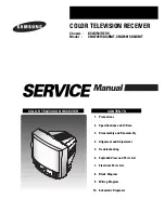


COLOR TELEVISION RECEIVER
Chassis :
KS1B(N)(REV.1)
Model :
CM27001SDX/KMT, CM27001SDS/KMT
COLOR TELEVISION RECEIVER
CONTENTS
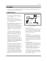
Precautions
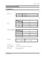
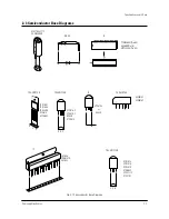
Specifications and IC Data
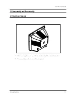
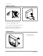
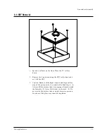
Disassembly and Reassembly
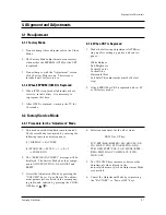
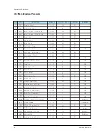
Alignment and Adjustment
Troubleshooting
Exploded View and Parts List
Electrical Parts List
Block Diagram
Wiring Diagram
Schematic Diagrams
1.
2.
3.
4.
5.
6.
7.
8.
9.
10.
Summary of Contents for CM27001SDS/KMT
Page 2: ...ELECTRONICS Samsung Electronics Co Ltd SEP 2001 Printed in Korea AA68 02135A ...
Page 10: ...2 4 MEMO ...
Page 14: ...3 4 Samsung Electronics MEMO ...
Page 33: ...7 6 Samsung Electronics MEMO ...
Page 36: ...9 2 MEMO ...
Page 40: ...Schematic Diagrams 10 4 Samsung Electronics 10 4 CRT ...


