background image

Electrical Parts List

Samsung Electronics

7-1

7-1 CM27001SDX/KMT, CM27001SDS/KMT

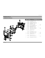
7. Electrical Parts List

Loc. No.

Code No.

Description ; Specification

Remark

ASSY PCB CHASSISPACK

1

*

AA93-00174A ASSY PCB CHASSISPACK;,KS1B,CM27001SDS/KM

..2

AA90-00136R ASSY-PACKING,PCB;KS2,3A,T/W,KS1B ALL,ALL

S.N.A

...3 CHASIS AA69-01403A WRAP VINYL-PACKING;SKD CHASSIS,LDPE,T0.0 S.N.A
..2

AA94-03680D ASSY PCB MAIN(OPT);CM27001SDS/KMT,KS1B

...3 C803

2401-001387

C-AL;470uF,20%,250V,GP,BK,25.4x40,1

...3 IC201S

AA09-00218A IC MICOM;TDA9387PS/N2H-OTP,CM27001,64P,3

...3 IC301

AA96-00623A ASSY H/S;-,POWER,AA62-00056A,LA7845

S.N.A

....4

0205-000129

GREASE-SILICON;SC102,JAPAN

S.N.A

....4

1204-000517

IC-VERTICAL DEF.;LA7845,SIP,7P,-,PLASTIC

....4

6003-000334

SCREW-TAPTITE;RH,+,2S,M3,L6,ZPC(YEL),SWR

S.N.A

....4

AA62-00056A HEAT SINK-PS;-,-,T1.0,-,41*35*70,D2,-,-,

S.N.A

...3 IC602

AA96-00244G ASSY H/S;-,AUDIO,AA62-00046A,TDA8944J,BR

S.N.A

....4

AA62-00046A HEAT SINK-PS;-,-,T1.0,-,D1(DREAM) 60X25X

S.N.A

....4

AA61-10162B BRACKET-IC;-,SBHG-1,T1.0,-,-,-,100

S.N.A

....4

6003-000335

SCREW-TAPTITE;RH,+,2S,M3,L8,ZPC(YEL),SWR

S.N.A

....4

1201-001741

IC-AUDIO AMP;TDA8944J,DBS,17P,937MIL,DUA

....4

0205-000129

GREASE-SILICON;SC102,JAPAN

S.N.A

...3 IC801S

AA96-50373H ASSY H/S;-,POWER,AA62-30181K,5Q1265RT

S.N.A

....4

0205-000129

GREASE-SILICON;SC102,JAPAN

S.N.A

....4

1203-002257

IC-PWM CONTROLLER;5Q12656RT,TO-220F-5L,5

....4

6003-000333

SCREW-TAPTITE;RH,+,2S,M3,L10,ZPC(YEL),SW

S.N.A

....4

AA62-30181K HEAT-SINK,ES;-,AL6063 EXTR.,2,WHT,40MM,-

S.N.A

...3 IC802

AA96-00245A ASSY H/S;-,-,AA62-00055A,KA7632,-

S.N.A

....4

1203-001939

IC-POSI.FIXED REG.;7632,SIP,10P,-,PLASTI

....4

AA62-00055A HEAT SINK-PS;-,-,T1.0,-,35*15*25,D1,-,-,

S.N.A

....4

6003-000334

SCREW-TAPTITE;RH,+,2S,M3,L6,ZPC(YEL),SWR

S.N.A

...3 JA701

3722-001428

JACK-PIN;6P/9P,3.4mm,NI,BLK,-

...3 LR401S

AA27-30003S COIL-LINEARLITY;-,54uH,YL81DR14x15,0.12m

...3 Q401

AA96-00624B ASSY H/S;-,POWER,AA62-00057A,KSC5802,K-M

....4

AA62-00057A HEAT SINK-PS;-,-,T1.0,-,41*20*60,D2,-,-,

S.N.A

....4

AA60-30001A WASHER-PLATE;M3,ID3.5,15X8.5,T1.0,-,SBHG

S.N.A

....4

6003-000333

SCREW-TAPTITE;RH,+,2S,M3,L10,ZPC(YEL),SW

S.N.A

....4

0502-001191

TR-POWER;KSC5802D,NPN,60000mW,TO-3P,ST,1

....4

0205-000129

GREASE-SILICON;SC102,JAPAN

S.N.A

...3 T444S

AA26-00013A TRANS-FLYBACK;-,FUH-29A001A(S),29,130V

...3 T801S

AA26-00044E TRANS SWITCHING;,CS21S5T,80~280V,PM5,PL5

...3

AA39-00046F LEAD CONNECTOR-ASSY;,1P,JUMPER,BLK,200MM

...3

AA39-20604A LEAD CONNECTOR-ASSY;,5/4P,YBNH250-09,YBN

...3

AA99-30231R ASSY-PCB ROBOT;     AA94-03680D    ,ER

S.N.A

....4 C821

2401-003633

C-AL;220UF,20%,160V,GP,ST,22X25MM,10

....4 CR402S 2301-001037

C-FILM,PPF;6.8nF,3%,1600V,TP,29x10x18,20

....4 CR403S 2306-000253

C-FILM,MPPF;7.2nF,5%,1.6KV,TP,28.5x18.5x

....4 CR406S 2306-000204

C-FILM,MPPF;430nF,5%,400V,TP,26x20.5x12.

....4 CX801S 2306-000318

C-FILM,MPPF;220nF,20%,250V,TP,-,22.5mm

....4 CX802S 2306-000318

C-FILM,MPPF;220nF,20%,250V,TP,-,22.5mm

....4 CY801S 2201-000446

C-CERAMIC,DISC;3.3nF,20%,400V,Y5U,TP,15x

....4 D801S

0402-001082

DIODE-BRIDGE;RBV406LFB,600V,4A,-

....4 D808

0402-001358

DIODE-RECTIFIER;FFPF10U60S,600V,10A,TO-2

....4 FP801S

3601-001012

FUSE;250V,4A,SLOW-BLOW,GLASS,5.2x20mm

....4 IC101

1204-001583

IC-IF CIRCUIT;U4468B,DIP,16P,-,PLASTIC,5

....4 IC202

1103-001209

IC-EEPROM;AT24C04-PC27 C,512Kx8Bit,DIP,8

....4 IC501

AA96-50311A ASSY-H/S;-,VIDEO,AA62-30175D,TDA6107Q,-

S.N.A

.....5

1201-001159

IC-VIDEO AMP;6107,ZSIP,9P,-,SINGLE,-,PLA

.....5

6003-000334

SCREW-TAPTITE;RH,+,2S,M3,L6,ZPC(YEL),SWR

S.N.A

.....5

AA62-30175D HEAT-SINK,PS;-,SECC,T1.0,-,33X15X30 FT-2

S.N.A

....4 IC601

1204-001594

IC-SOUND PROCESSOR;MSP3440G-B6,SDIP,52P,

....4 L808

AA27-00098A COIL CHOKE;-,-,24uH,10%,-,0.1,3.0A,DR10X

....4 LD201

AA96-00555A ASSY LED GUIDE;-,-,UEX-LD-030,GREEN

S.N.A

....4 LX801S

AA29-30002F FILTER-LINE NOISE;-,6mH,2.45A,-,-

....4 NT802S 1404-001045

THERMISTOR-NTC;4.7ohm,15%,2900K,35.0mW,T

....4 PC801S 0604-001038

PHOTO-COUPLER;TR,130-260%,200mW,DIP-4,ST

....4 PT801S

1404-001246

THERMISTOR-PTC;1.5OHM,+30/-20,110V,140VA

....4 RL801S

3501-001040

RELAY-POWER;12VDC,500mW,10A,1FormA,15mS,

....4 RM201

AA59-60001U MODULE-REMOCON;-,ORC-50VF/SR-12V,38KHz,9

....4 SF101S

2904-000287

FILTER-SAW AV;45.75MHz,SIP5K,ST,14dB,M/N

....4 SF103S

2904-001255

FILTER-SAW AV;45.75MHz,SIP5K,ST,12.2dB,M

....4 SW201

3404-001004

SWITCH-TACT;12V,50mA,160gf,8.4x22.7mm,SP

....4 T401A

AA26-50001R TRANS-HORIZ.DRIVE;-,-,-,80MH,-,-,520UH,-

....4 TU01S

AA40-00088A TUNER;TAEC-H005F(F),NTSC,181CH,45.75MHZ,

....4 V999S

3704-001105

SOCKET-CRT;11P,20PI,26.5PI,NI,-

....4

AA99-10225D ASSY-PCB MAIN,AUTO; AA99-30231R    ,V

S.N.A

.....5 C101

2401-000962

C-AL;22uF,20%,50V,GP,TP,5x11,5

.....5 C102

2301-000383

C-FILM,PEF;10nF,5%,50V,TP,6x7x3.2mm,5mm

.....5 C103

2401-002594

C-AL;220uF,20%,16V,GP,TP,8x11.5,5

.....5 C104

2401-000480

C-AL;10uF,20%,50V,GP,TP,5x11,5

.....5 C105

2305-000665

C-FILM,MPEF;100nF,5%,63V,TP,7.5x4.0x5.0m

.....5 C106

2401-002619

C-AL;47uF,20%,25V,GP,TP,5x11,5

.....5 C108

2202-000127

C-CERAMIC,MLC-AXIAL;10nF,+80-20%,25V,Y5V

.....5 C109

2202-000127

C-CERAMIC,MLC-AXIAL;10nF,+80-20%,25V,Y5V

.....5 C110

2202-000127

C-CERAMIC,MLC-AXIAL;10nF,+80-20%,25V,Y5V

.....5 C114

2401-002619

C-AL;47uF,20%,25V,GP,TP,5x11,5

.....5 C115

2305-000665

C-FILM,MPEF;100nF,5%,63V,TP,7.5x4.0x5.0m

.....5 C116

2305-000412

C-FILM,MPEF;470nF,5%,63V,TP,-,5mm

.....5 C117

2401-000027

C-AL;4.7uF,20%,50V,GP,TP,5x11,5

.....5 C118

2401-000027

C-AL;4.7uF,20%,50V,GP,TP,5x11,5

.....5 C120

2202-000127

C-CERAMIC,MLC-AXIAL;10nF,+80-20%,25V,Y5V

.....5 C127

2202-000286

C-CERAMIC,MLC-AXIAL;56pF,5%,50V,SL,TP,1.

.....5 C201

2401-000302

C-AL;100uF,20%,25V,GP,TP,6.3x11,5

.....5 C203

2202-000127

C-CERAMIC,MLC-AXIAL;10nF,+80-20%,25V,Y5V

.....5 C204

2305-000411

C-FILM,MPEF;470nF,5%,50V,TP,7.3x4.8x5.5m

.....5 C205

2202-000796

C-CERAMIC,MLC-AXIAL;1NF,10%,50V,Y5P,TP,3

.....5 C206

2305-000665

C-FILM,MPEF;100nF,5%,63V,TP,7.5x4.0x5.0m

.....5 C207

2401-000302

C-AL;100uF,20%,25V,GP,TP,6.3x11,5

.....5 C208

2201-000573

C-CERAMIC,DISC;0.047nF,5%,50V,NP0,TP,5x3

.....5 C209

2305-000665

C-FILM,MPEF;100nF,5%,63V,TP,7.5x4.0x5.0m

.....5 C210

2201-000573

C-CERAMIC,DISC;0.047nF,5%,50V,NP0,TP,5x3

.....5 C211

2401-000302

C-AL;100uF,20%,25V,GP,TP,6.3x11,5

.....5 C212

2401-000480

C-AL;10uF,20%,50V,GP,TP,5x11,5

.....5 C213

2305-000289

C-FILM,MPEF;220nF,5%,63V,TP,-,5mm

.....5 C218

2305-000411

C-FILM,MPEF;470nF,5%,50V,TP,7.3x4.8x5.5m

.....5 C219

2305-000665

C-FILM,MPEF;100nF,5%,63V,TP,7.5x4.0x5.0m

.....5 C220

2401-000302

C-AL;100uF,20%,25V,GP,TP,6.3x11,5

.....5 C221

2202-000849

C-CERAMIC,MLC-AXIAL;18pF,5%,50V,CH,TP,3.

.....5 C222

2305-000665

C-FILM,MPEF;100nF,5%,63V,TP,7.5x4.0x5.0m

.....5 C223

2202-000632

C-CERAMIC,MLC-AXIAL;100nF,20%,50V,Z5U,TP

.....5 C225

2305-000289

C-FILM,MPEF;220nF,5%,63V,TP,-,5mm

.....5 C226

2401-000302

C-AL;100uF,20%,25V,GP,TP,6.3x11,5

.....5 C227

2401-000302

C-AL;100uF,20%,25V,GP,TP,6.3x11,5

.....5 C229

2305-000665

C-FILM,MPEF;100nF,5%,63V,TP,7.5x4.0x5.0m

.....5 C231

2305-000289

C-FILM,MPEF;220nF,5%,63V,TP,-,5mm

.....5 C232

2305-000665

C-FILM,MPEF;100nF,5%,63V,TP,7.5x4.0x5.0m

.....5 C233

2401-000302

C-AL;100uF,20%,25V,GP,TP,6.3x11,5

.....5 C234

2401-000660

C-AL;2.2uF,20%,50V,GP,TP,5x11,5

.....5 C235

2301-000342

C-FILM,PEF;2.2nF,5%,50V,TP,7.4x3.9x13mm,

.....5 C236

2305-000289

C-FILM,MPEF;220nF,5%,63V,TP,-,5mm

.....5 C237

2301-000445

C-FILM,PEF;4.7nF,5%,50V,TP,5.5x7x3mm,5mm

.....5 C238

2401-000603

C-AL;1uF,20%,50V,GP,TP,5x11,5

.....5 C239

2401-000480

C-AL;10uF,20%,50V,GP,TP,5x11,5

.....5 C240

2305-000665

C-FILM,MPEF;100nF,5%,63V,TP,7.5x4.0x5.0m

.....5 C241

2401-000758

C-AL;220nF,20%,50V,GP,TP,5x11,5

.....5 C242

2202-000796

C-CERAMIC,MLC-AXIAL;1NF,10%,50V,Y5P,TP,3

.....5 C243

2202-000796

C-CERAMIC,MLC-AXIAL;1NF,10%,50V,Y5P,TP,3

.....5 C244

2309-000138

C-FILM,PE-PPF;100nF,5%,50V,TP,20x16x8.5,

.....5 C245

2301-000224

C-FILM,PEF;22nF,5%,50V,TP,7.4x3.9x13mm,5

.....5 C247

2401-000962

C-AL;22uF,20%,50V,GP,TP,5x11,5

.....5 C248

2202-000829

C-CERAMIC,MLC-AXIAL;.82NF,10%,50V,Y5P,TP

.....5 C249

2301-000445

C-FILM,PEF;4.7nF,5%,50V,TP,5.5x7x3mm,5mm

.....5 C253

2401-002619

C-AL;47uF,20%,25V,GP,TP,5x11,5

.....5 C301

2301-000254

C-FILM,PEF;39nF,5%,50V,TP,7.5x3.5x6.5mm,

.....5 C302

2201-000247

C-CERAMIC,DISC;0.015nF,5%,50V,NP0,TP,5x3

.....5 C303

2401-000360

C-AL;100uF,20%,50V,GP,TP,8x11.5,5

Loc. No.

Code No.

Description ; Specification

Remark

Summary of Contents for CM27001SDS/KMT

Page 1: ...7001SDS KMT COLOR TELEVISION RECEIVER CONTENTS Precautions Specifications and IC Data Disassembly and Reassembly Alignment and Adjustment Troubleshooting Exploded View and Parts List Electrical Parts List Block Diagram Wiring Diagram Schematic Diagrams 1 2 3 4 5 6 7 8 9 10 ...

Page 2: ...ELECTRONICS Samsung Electronics Co Ltd SEP 2001 Printed in Korea AA68 02135A ...

Page 3: ...dle brackets metal cabinets screwheads and control shafts The current measured should not exceed 0 5 milliamp Reverse the power plug prongs in the AC outlet and repeat the test Fig 1 1 AC Leakage Test 6 Antenna Cold Check With the unit s AC plug disconnected from the AC source connect an electrical jumper across the two AC prongs Connect one lead of the ohmmeter to an AC prong Connect the other le...

Page 4: ...t appear to have overheated or that are otherwise damaged should be replaced with parts that meet the original specifications Always determine the cause of damage or overheat ing and correct any potential hazards 15 Observe the original lead dress especially near the following areas Antenna wiring sharp edges and especially the AC and high voltage power supplies Always inspect for pinched out of p...

Page 5: ...g and accessible conductive parts examples metal panels input terminals and earphone jacks 6 Insulation Checking Procedure Disconnect the power cord from the AC source and turn the power switch ON Connect an insulation resistance meter 500V to the blades of the AC plug The insulation resistance between each blade of the AC plug and accessible conductive parts see above should be greater than 1 meg...

Page 6: ...trical charges that damage ESDs 5 Use only a grounded tip soldering iron when soldering or unsoldering ESDs 6 Use only an anti static solder removal device Many solder removal devices are not rated as anti static these can accumulate sufficient electrical charge to damage ESDs 7 Do not remove a replacement ESD from its protective package until you are ready to install it Most replacement ESDs are ...

Page 7: ...ower Requirements Antenna Input Impedance Speaker Impedance NTSC NTSC 2 13 14 69 45 75 41 25 42 18 System Band VHF UHF 1 125 CABLE SYSTEM IF Carrier Frequency Picture IF Carrier Sound IF Carrier Color Sub Carrier MODEL CT 29 Inch AC 120V 60Hz VHF UHF Telescopic dipole antenna 75 ohm unbalanced type 8 ohm 5W 5W Dual Type SYSTEM NTSC ONLY A68QDN891X001 29Inch 1 0R 380MG ...

Page 8: ...e Up IC202 24C04 EEPROM PC801S TCET1108 LTV817B PHOTO COUPLER SPM426AN TDA9387 English Spanish French IC201S Philips Philips Philips FIAIR CHILD VERTICAL OUTPUT LA7845 TDA8944 IC301 IC602 SOUND AMP 5W x 2CH IC801S KA5Q1265R POWER IC STR IC802 KA7632 CUSTOM REGULATOR 5V 8V 3 3V IC101 U4468B SIF IC TEMIC IC601 MSP3440G Sound Processor Micronas Sanyo SEC ...

Page 9: ...N Pin 64 U4468B Pin 16 MSP3440G Pin 52 IC TRANSISTOR LA7845 TDA6107Q KA7632 TRANSISTOR TRANSISTOR 2SD1651 2SD1650 2SD2499 KSA614 KSC5802 B C E E B C KSC815 Y KSA539 Y BC548 KTC9014 IC UPC574J or KA33V SAW FILTER E C B KSR1012 KSR1010 KSR2010 KTD863 Y KSC2331 Y KTC3197 1 1 1 M3951M M9261M Fig 2 1 Semiconductor Base Diagrams ...

Page 10: ...2 4 MEMO ...

Page 11: ...reassembly Samsung Electronics 3 1 3 Disassembly and Reassembly 3 1 Back Cover Removal 1 After removing the screws press the tension rib and pull the cabinet backwards 2 To reassemble press the tension rib see diagram ...

Page 12: ...cket board from the CRT neck 2 Remove the Anode Cap from the CRT 3 Remove the main board by pulling it with both hands Warning The FBT is charged with high voltage Before removing the Anode Cap discharge the voltage through one of the heat sinks on the main board 1 Remove the speaker by pressing the tension rib ...

Page 13: ...RT to the front cabi net Lift the CRT 3 Caution Because of the high vacuum and large surface area of the picture tube be careful while handling it 1 Always lift the picture tube by grasping it firmly around the faceplate 2 Never lift the tube by its neck 3 Do not scratch the picture tube or apply excessive pressure Fractures of the glass may cause an implosion ...

Page 14: ...3 4 Samsung Electronics MEMO ...

Page 15: ...t be the last step 2 If the EEPROM or CRT is replaced and set SC as 30 factory mode 4 2 Factory Service Mode 4 2 1 Procedure for the Adjustment Mode 1 This mode uses the standard remote control The Service Mode is activated by entering the following remote control sequence 1 DISPLAY FACTORY 2 STAND BY MUTE 1 8 2 POWER ON 2 The SERVICE FACTORY message will be displayed The Service Mode has four com...

Page 16: ... NSR N TSC Sub c ol or 0 23 SCBT Screen Brighrtness 0 63 VOL Vol ume pre s et t i ng 0 63 0 63 0 63 CAP Caption Position Melody Sound Volume Ratio Pre overshoot Ratio Pre overshoot Window Selection Sound PLL IF AGC Speed Offset IF Demodulator Soft Clipping Level Peak White Limitting Matrix USA Automatic Gain Control MVOL RP00 RP01 FMWS AGC1 OMD SCL PWL MUS AGC 15 8 35 32 40 25 42 30 31 25 32 30 9 ...

Page 17: ... AUTO POWER AUDIO MUTE LANGUAGE HOTEL MODE BULE SCREEN 2 nd SIF V CHIP SETTING OFF STEREO OFF NOR ZOOM OFF ON ENGLISH OFF OFF INTERNAL ON Video Mute On Off changing the channel Audio Option Mono Steeo E W Option Picture Size Option Master S w Option Audio Mute On Off without signal Inital Language agter Factory Reset Hotel mode On Off Bule Screen On Off without signal SIF Option at Mono sound V CH...

Page 18: ...d on Make sure that the power cord is disconnected before replacing any parts 8 To protect against shock hazard use an isola tion transformer 4 3 2 Automatic Degaussing A degaussing coil is mounted around the pic ture tube so that external degaussing after moving the TV should be unnecessary But the receiver must be properly degaussed upon installation The degaussing coil operates for about 1 sec ...

Page 19: ...lloscope probe 2 Input a gray scale pattern Use a pattern gen erator PM5518 3 Use the P mode key on the remote control for the STANDARD picture 4 Adjust the Screen VR on the FBT so that the voltage on the oscilloscope becomes 125 2 5V See Fig 4 1 4 3 6 Purity Adjustment 1 Warm up the receiver for at least 20 minutes 2 Plug in the CRT deflection yoke and tighten the clamp screw 3 Plug the convergen...

Page 20: ... Adjustment 31m m Vertical Green Belt Fig 4 4 1 2 a Set up 1 Warm up the TV for at least 30 minutes in the Aging Mode OSD White This mode is dis played by entering the following sequence DISPLAY FACTORY FACTORY 2 Input a Toshiba pattern b Low Light Adjustment 1 Set SBT to 1 0 fL in the Factory Service Mode with using CA100 See Fig 4 4 2 Adjust RG BG so that the levels are suitable to each local ar...

Page 21: ...and the blue vertical lines in the center area of the screen 5 Turn the both tabs at the same time keeping the angle constant and superimpose the red and blue horizontal line in the center of the screen 6 Adjust the two tab pairs of the 6 pole magnets to superimpose the red and blue line onto the green Changing the angle affects the vertical lines and rotating both magnets affects the horizontal l...

Page 22: ...on head circle becomes oval 3 Adjust with VA Vertical Amplitude so that the top margin of the picture is 4 Fig 4 7 4 Adjust with VSL Vertical Slope so that the bottom margin of the picture is 4 Fig 4 8 5 Adjust with HS Horizontal Shift so that the lion head pattern and CRT centers are aligned Fig 4 9 6 Adjust HS Horizontal Shift so that the left and right margins of the picture are 5 Alignment and...

Page 23: ...al Abnormal Abnormal Abnormal Counect the Power code Check the Power LED Check the X tal SDA SCL port of IC201S Check the 33 Pin H Drive of IC201S Check the 130V A Line Check the 3 3V A 8V A Line of IC201S Check Replace IC802 Replace IC201 S Check the FBT D808 Check the 12 5V A Line Check the FD802S IC801S or AC Fuse Check Replace Q401 ...

Page 24: ...rmal Abnormal Check RK GK BK Signal Check R G B Signal into CRT PCB Check the resistance of R512 Check IC201S Pin 49 V GUARD Pin50 IK Check IC501 B 180V B Check the Voltage of heater Check CRT and FBT Check Replace D407 FBT Re Adjust Screen Voltage Replace R512 Check CRT and FBT Check Replace IC201S Check Replace R418 R513 D503 Check IC201S Pin 51 52 53 R G B ...

Page 25: ...ire Check Replace IC601 Check B Line 5V B 8V B Check IC101 TUNER Check Replace IC201S See No Power Check IC101 TUNER Replace IC602 Replace IC610 R611 Replace FD801S D805 Check IC602 Pin8 9 Check IC601 Pin47 SIF Check IC601 B Check IC201S Pin32 SIF Check IC602 B Check R610 R611 Check FD801S D805 Abnormal Abnormal Abnormal Abnormal Abnormal Abnormal Abnormal Abnormal MONO STEREO ...

Page 26: ...lectronics Troubleshooting 5 4 Horizontal Lines Appear or Screen Normal Normal Abnormal Abnormal Check R413 R414 D405 D406 Check IC201S Check IC201S Pin 21 22 VDN VDP Check IC301 B 16V C 13 5V C Check Replace IC301 ...

Page 27: ... V2 NTR 1 1 1 6 AA64 40473A INDICATOR LED 683B PMMA CLEAR HB 1 1 7 AA64 10732A KNOB CONTROL 683B ABS HB BLK 1 1 8 6003 001026 SCREW TAPTITE RH B M4 L15 ZPC BLK SWR 2 KC CF 1 9 6003 001026 SCREW TAPTITE RH B M4 L15 ZPC BLK SWR 8 SPK CF 1 10 3001 001071 SPEAKER 5W 8ohm 90dB 180Hz 2 1 11 AA61 40010B BOSS WING HIPS BLK V0 1 2 AA03 00147A CRT COLOR A68QDN891X001 29 1 0R 42 5 3 1 2 1 AA60 10050R SCREW A...

Page 28: ...RL801S 3501 001040 RELAY POWER 12VDC 500mW 10A 1FormA 15mS 4 RM201 AA59 60001U MODULE REMOCON ORC 50VF SR 12V 38KHz 9 4 SF101S 2904 000287 FILTER SAW AV 45 75MHz SIP5K ST 14dB M N 4 SF103S 2904 001255 FILTER SAW AV 45 75MHz SIP5K ST 12 2dB M 4 SW201 3404 001004 SWITCH TACT 12V 50mA 160gf 8 4x22 7mm SP 4 T401A AA26 50001R TRANS HORIZ DRIVE 80MH 520UH 4 TU01S AA40 00088A TUNER TAEC H005F F NTSC 181C...

Page 29: ...AL 47uF 20 50V GP TP 6 3x11 5 5 CN602 3711 002643 CONNECTOR HEADER BOX 4P 1R 2 5mm STRAIGH 5 CR01S 2201 000556 C CERAMIC DISC 0 47nF 10 500V Y5P TP 5 5 CR02S 2401 000480 C AL 10uF 20 50V GP TP 5x11 5 5 CR03S 2401 000480 C AL 10uF 20 50V GP TP 5x11 5 5 CR405S 2201 000132 C CERAMIC DISC 0 1nF 10 500V Y5P TP 6 5 5 D206 0401 000005 DIODE SWITCHING 1N4148 100V 200mA DO 35 5 D208 2701 000211 INDUCTOR AX...

Page 30: ...00281 R CARBON 100OHM 5 1 8W AA TP 1 8X3 2MM 5 R232 2001 000281 R CARBON 100OHM 5 1 8W AA TP 1 8X3 2MM 5 R244 2001 000281 R CARBON 100OHM 5 1 8W AA TP 1 8X3 2MM 5 R245 2001 000591 R CARBON 3 3KOHM 5 1 8W AA TP 1 8X3 2MM 5 R246 2001 000793 R CARBON 47OHM 5 1 8W AA TP 1 8X3 2MM 5 R247 2001 000969 R CARBON 75OHM 5 1 8W AA TP 1 8X3 2MM 5 R248 2001 000325 R CARBON 120OHM 5 1 8W AA TP 1 8X3 2MM 5 R249 2...

Page 31: ...MM 5 RR03S 2001 001128 R CARBON S 30KOHM 5 1 2W AA TP 2 4X6 4 5 RR04S 2001 000009 R CARBON 20KOHM 5 1 8W AA TP 1 8X3 2MM 5 RR05S 2004 001382 R METAL S 13Kohm 1 1 2W AA TP 2 4x6 4m 5 RR07S 2001 000066 R CARBON S 10KOHM 5 1 2W AA TP 2 4X6 4 5 RR401S 2004 001390 R METAL S 1Kohm 2 1 2W AA TP 2 4x6 4mm 5 RY801S 2002 001013 R COMPOSITION 4 7Mohm 5 1 2W AA TP 3 7x 5 SW202 3404 000244 SWITCH TACT 15V 20mA...

Page 32: ... WIRE P 29INCH NTSC 2PWH 1P K S N A REMOCON 1 AA59 10111E REMOCON TM59 SZM386ET 24 G6671B CURTISM Electrical Parts List Samsung Electronics 7 5 Loc No Code No Description Specification Remark Loc No Code No Description Specification Remark ...

Page 33: ...7 6 Samsung Electronics MEMO ...

Page 34: ...65R S W MULTI REGULATOR 3 3V TO MCU 8V TO MCU I 2C AUDIO A M P TDA 8944J F SOUND PROCESSOR MSP3440G BT 21 F 25 29 FUH S VIDEO I 2C VIDEO SI F SA W M9261M U4468B IC M C U SP M 426A N 2 3 2 4 21 22 50 53 2 3 45 48 38 42 2 41 42 30 31 R L OUT 24 25 STEREO 12 S W 2 1 P r e A M P R G B FB H OUT TR 3 3 16 5V TO Ver A M P 180V TO C RT Heat TO C RT 13V TO SOUND AMP 8R 2E A KA7632 KSC 5802 Option Q 29A001A...

Page 35: ...KS1B Wiring Diagram CRT PCB 8 7 6 5 4 3 1 2 SOUND L IN SOUND R IN SOUND L OUT SOUND R OUT VIDEO IN GND VIDEO OUT GND 1 2 3 4 HEAT N C GND 180V CN501B 1 2 5 3 4 GND IK G OUT B OUT R OUT CN501A CN602 CN701 1 2 3 4 L OUT R OUT L OUT R OUT POWER CORD ...

Page 36: ...9 2 MEMO ...

Page 37: ...TP03 TP04 TP05 TP06 TP12 TP11 TP10 TP08 TP09 TP07 Schematic Diagrams 10 1 Samsung Electronics 10 Schematic Diagrams 10 1 MAIN 1 3 Power Line Signal Line TP01 TP02 TP04 TP05 TP07 TP08 TP10 TP11 TP03 TP06 TP09 TP12 ...

Page 38: ...Schematic Diagrams 10 2 Samsung Electronics 10 2 MAIN 2 3 TP02 TP01 TP05 TP04 TP03 TP01 TP02 Power Line Signal Line TP03 TP04 TP05 ...

Page 39: ...Schematic Diagrams 10 3 Samsung Electronics 10 3 MAIN 3 3 TP02 TP01 TP01 TP02 Power Line Signal Line ...

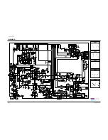
Page 40: ...Schematic Diagrams 10 4 Samsung Electronics 10 4 CRT ...

Reviews: