background image

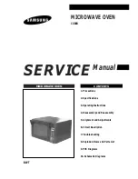
MICROWAVE OVEN

CO88R

SERVICE 

Manual

MICROWAVE OVEN

CONTENTS

1. Precautions

2. Specifications

3. Operating Instructions

4. Disassembly and Reassembly

5. Alignment and Adjustments

6. Circuit Description

7. Troubleshooting

8. Exploded Views and Parts List

9. PCB Diagrams

10. Schematic Diagrams

BWT

Summary of Contents for CO88R

Page 1: ...AVE OVEN CONTENTS 1 Precautions 2 Specifications 3 Operating Instructions 4 Disassembly and Reassembly 5 Alignment and Adjustments 6 Circuit Description 7 Troubleshooting 8 Exploded Views and Parts List 9 PCB Diagrams 10 Schematic Diagrams BWT ...

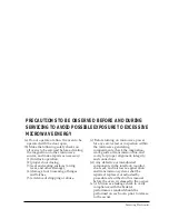
Page 2: ... or inspection within the microwave generating compartments check the magnetron wave guide or transmission line and cavity for proper alignment integrity and connections d Any defective or misadjusted components in the interlock monitor door seal and microwave generation and transmission systems shall be repaired replaced or adjusted by procedures described in this manual before the oven is releas...

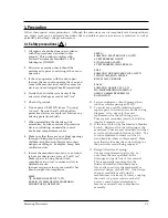
Page 3: ...LECTRONICS CO LTD ST PETERSBERG OFFICE 5 1TALIANSKAYASTR ST PETERSBERG 191011 RUSSIA SUSC SAMSUNG UKRAINE SERVICE CO LTD 7 ZHILIYANSKAYA STREET KIEV 252033 UKRAINE SALSC SAMSUNG ALMATY SVC CO 52A MICROREGION ORIBITA 3 ALMATY 480043 REPUBLIC OF KAZAHSTAN 10 Service technicians should remove their watches while repairing an MWO 11 To avoid any possible radiation hazard replace parts in accordance wi...

Page 4: ...ment components that have the same ratings especially for flame resistance and dielectric strength specifications A replacement part that does not have the same safety characteristics as the original might create shock fire or other hazards 1 High Voltage Warning Do not attempt to measureany of the high voltages this includes the filament voltage of the magnetron High voltage is present during any...

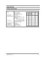
Page 5: ...r Heating Element 1 500W OUTPUT POWER FROM 70W TO 700W 10 LEVEL POWER IEC 705 TEST PROCEDURE OPERATING FREQUENCY 2 450MHz MAGNETRON OM75PH 21 ESS COOLING METHOD COOLING FAN MOTOR OUTSIDE DIMENSIONS 498 W x 330 H x 461 D POWER LEVEL Output 10 70W 4 sec 26 sec 20 140W 7 sec 23 sec 30 210W 10 sec 20 sec 40 280W 13 sec 17 sec 50 3505W 16 sec 14 sec 60 420W 19 sec 11 sec 70 490W 22 sec 8 sec 80 560W 25...

Page 6: ...CCA RUHNOE MEN VREMQ HASY START 1MIN 3 Operating Instructions 3 1 Control Panel Samsung Electronics 3 1 DISPLAY SENSOR REHEAT FEATURE SELECTION SENSOR COOKING REHEAT DEFROSTING TIME ADJUSTMENT BUTTONS TEMPERATURE CONTROL BUTTONS POWER LEVEL SELECTION START 1MIN KNOB CANCELLATION BUTTON CLOCK SETTING GRILL MODE SELECTION MICROWAVE MODE SELECTION CONVECTION MODE SELECTION AUTOMATIC COOKING MENU BUTT...

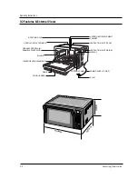
Page 7: ...ructions UPPER HEATING ELEMENT CABINET VENTILATION SLOTS TOP VENTILATION SLOTS SIDE DISPLAY POWER SUPPLY CORD PLUG DOOR HANDLE DOOR LOWER HEATING ELEMENT RUNGS CERAMIC PROCELAIN ENAMELED INTERIOR VENTILATION SLOTS BACK ROTATING AXLE CONTROL PANEL 498MM 4 6 1 M M 330MM ...

Page 8: ...4 2 2 Remove the connector CN6 above the PC board 3 Remove four screws for PC board fixing 4 Remove parts like toenail on the operating panel and then the PC board A 5 Remove eleven screws for PC board fixing 6 Remove the PC board B from the operating panel 7 Remove two screws for volume installing plate attachment 4 Disassembly and Reassembly 4 1 Removal of Outer Panel Samsung Electronics 4 1 4 2...

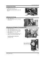
Page 9: ...pport heater two pieces 5 Remove the upper heater 4 4 Replacement of Temperature Seneor 4 5 Replacement of Gas Sensor 4 6 Replacement of Upper Heater Bkt cover heater U Gasket stopper Gasket Plate spring Support heater 4 2 Samsung Electronics Disassembly and Reassembly Temperature sensor Temperature sensor attachment screws GAS sensor attachment screws GAS sensor A B SUPPORT HEATER Hold on A part ...

Page 10: ... 3 Remove the back panel Screw seven piece 4 Remove the BKT HVT Screw upper resp lower each two 5 Remove the magnetron attachment screws four pieces and then the magnetron 6 Thermo switch is removed together with Care the high tension voltage when removing wiring 4 8 Replacement of Lamp 4 9 Replacement of Magnetron Thermometal switch Disassembly and Reassembly LAMP LAMP attachment screw Support MG...

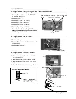
Page 11: ...d right each one 3 Remove the spring stopper one at the lower left 4 Open the door to remove it pressing lefthand 4 10 Replacement of High Voltage Trans Condenser and Diode 4 11 Replacement of Noise Filter 4 4 Samsung Electronics Disassembly and Reassembly HIGH VOLTAGE TRANSFORMER BKT HVC HIGH VOLTAGE CONDENSER HIGH VOLTAGE DIODE BKT HVR BKT HVT Noise Filter attachment screws ARM SLIDER RIGHT ARM ...

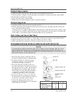
Page 12: ...er 1 Remove the wiring fan motor low tension transformer primary and secondary 2 Remove the screws two for fan motor and two for low voltage transformer 3 Remove the fan heater 4 Remove the low voltage transformer 4 13 Replacement of Lower Heater and Weight Sensor assembly Samsung Electronics 4 5 4 14 Replacement of Fan Motor and Lower Voltage Transformer Disassembly and Reassembly Base plate fixi...

Page 13: ... fully press the button of switch 1 and then fasten up the latch fixing screws Note A gap between the door and front panel may be formed if the pressing is too hard 2 Fasten the latch fixing screws in this state 4 15 Replacement of Body Latch Samsung Electronics 4 6 Disassembly and Reassembly Latch FRONT PANEL OPEN CLOSE Latch fixing screw 1 LEVER A Switch 1 Switch 2 Monitor switch Latch fixing sc...

Page 14: ...tween each filament terminal and the magnetron case should read open 1 The low voltage transformer is located on the base plate 2 Remove the low voltage transformer from the base plate and check continuity 3 Normal resistor readings a shown in the table PRECAUTION 1 High voltage is present at the high voltage terminals during any cook cycle 2 Do not attempt to measurement the high voltage 3 Before...

Page 15: ... assembly adjust the Latch Body by moving it so that the oven door has vo play Check for play by pulling the door assembly Make sure that the latch keys move smoothly after adjustment is completed Completely tighten the screws holding the latch body to the oven assembly 4 Reconnect to Monitor switch and re check that the the monitor circuit and all latch switches are secured see components test pr...

Page 16: ...er test should be done if temperature rise is marginal NOTE 2 Output power in watts is computed by multiplying the temperature rise step E by a factor of 71 times the centigrade temperature The microwave heat distribution can be checked indirectly by measuring the water temperature rise at certain positions in the oven 1 Prepare five beakers made of Pyrex each having 100 milliliters capacity 2 Mea...

Page 17: ...of the manufacturer of the microwave energy survey meter Samsung Electronics 5 4 Alignment and Adjustments 1 Pour 275 15cc of 20 5 68 9 water in a beaker which is graduated to 600cc and place the beaker in the center of the oven 2 Start to operate the oven and measure the leakage by using a microwave energy survey meter 3 Set survey meter with dual ranges to 2 450MHz 4 When measuring the leakage a...

Page 18: ...3 4V is applied to the magnetron to heat the magnetron filament through two noise preventing choke coils 6 High voltage 2 230 volts AC is generated by the high voltage transformer secondary This secondary voltage is increased by the diode and high voltage capacitor This resultant DC voltage is then applied to the anode of the magnetron As shown in Fig 2 the first half cycle of the high voltage pro...

Page 19: ...pon opening the door the contacts of the primary and secondary interlock switch open and the contacts of interlock monitor switch close 5 If the contacts of primary interlock switch do not function properly the fuse blows out because of the large current surge caused by the monitor switch activation which stops magnetron oscillation see Fig 3 6 5 When the CANCEL pad is touched during cooking 1 Tou...

Page 20: ...cation of weight sensor 0 apprx 4000g 7 1 2 Method of adjusting 0 point Operation Display in operation 1 Plug in the cord 2 Open the door to put rotating plate and round dish into range 3 Close the door and press the P L key and key simultaneously 4 Open the door to put a weight of balance of 1kg or two of 500g on the center of round dish Note 1 5 Close the door and press simultaneously the P L an...

Page 21: ...s exerted on axle the plate spring sensor plate on driving axle will come down to enlarge the gap away from the sensor electric pole on the fixed PC board and thus the electrostatic capacity will be changed by which the oscillation of weight sensor PC board changed and it allows to measure the weight by 7 1 4 Details of functions of Weight Sensor L o a d axle PC Sensor pole Fixed axle Driving axle...

Page 22: ...le and oscillating frequency kHz 7 1 4 4 Wiring diagram for measuring frequency 1 Do not apply heavy load or pressure on the rotating dish The weight sensor directly contact the rotating dish Putting food that exceeds 4kg Total can damage the weight sensor 2 Use only genuine replacements that fit the model C E rotating dish and supporter Frequency kHz 0 0 V 5 V 100pF 1000g 36 g Load At 0 point Osc...

Page 23: ...ormal The upper heater and lower cavity emit heat Do not directly touch the Upper Heater Lower Heater and plate that become hot during or remain hot after heating Error indication Cause of occurrence Management method Remarks E0 Gas sensor open short Check the connection and Automatic sensor value cooking reheating reheating between 6 and 211 Put the power switch again and and use it after 10 minu...

Page 24: ...e during servicing do not damage the wire Adjust and arrange the wire and tie heat proof onsulated tie after the repairs have been completed 7 3 1Operation in manual mode of microwave The manual mode of MWO comprises 10 power level modes one is that the magnetron works in full time at 600W output in manual operation which is the range high and another is that the magnetron repeats On Off operation...

Page 25: ...ich measures weight of food 7 3 3 1 Operation of temperature sensor thermostat for cooking Pizza Cake Make a cooking at an optimum temperature which is controlled by thermostat according to variety of foods as well as in optimum cooking time Cooking state can be regulated with the Regulation for completion more and less keys When this process begins the remained time is displayed on panel 7 3 4 Op...

Page 26: ...power relay also NOTE 2 When HVTransformer is replaced check diode and magnetron also Oven does not accept 1 Key input is not in Sequence Refer to operation procedure key input Program 2 Open or loose connection of sub PCB to main PCB 3 Squeeted buttons 4 Defective Ass y PCB Replace PCB main 1 Off alignment of latch switches Adjust door and latch switches 2 Open or loose connection of high voltage...

Page 27: ...table motor 2 Defective turntable motor Replace turntable motor Fan motor does not rotate 1 Defective fan motor Replace fan motor 2 Defective fan motor or ass y PCB Replace PCB main Oven stops operation during cooking 1 Open or loose wiring of primary Adjust door and latch switches interlock switch 2 Operation of thermal cutout Magnetron Sparks 1 Metallic ware or cooking dishes Inform the customer...

Page 28: ...ry switch 3 Applicability of parts Check that exact replacement parts are being used AC 230V 4 Placement of Check for looseness jamming or terminal insertion lead wire of the lead wire check that there are no shorts to ground 5 Connection of Check the connection between he screw and bolt screw and bolt 6 Alien substance Check for a cut line within the equipment insertion check combustible foreign ...

Page 29: ...27 M2 M3 M9 M4 M5 M24 M23 M26 M41 M42 M43 M44 M39 M53 M57 M62 M57 M51 M50 M54 M55 M40 B6 B3 B2 M38 M56 M64 B5 B4 B4 B1 M7 M11 M25 M29 M28 M39 M8 M37 M34 M31 M30 M32 M33 M6 M15 M61 M16 M1 M58 M36 M36 M17 M14 M19 M46 M45 M47 M49 M52 M39 M48 M48 M10 M12 M59 M60 M13 M22 M20 M21 M18 yyy yyy yyy yyy yyy yyy ...

Page 30: ...20W 7 5 7 0 1 M 24 DE63 20061A GASKET HEATER BRASS T1 0 W15 L57 1 M 25 DE71 60374A COVER MGT MICASHEET T0 5 W56 5 L115 1 M 26 DE92 90475C ASSY ARM SLIDER RE CH1 CO88R BURR_DELETE NI CR 1 M 27 DE66 10063E ARM SLIDER SPC1 T2 0 W65 L148 BURR_DELETE 1 M 28 DE62 90096A ADIABATIC RIGHT SUPERFINEINSULATION T5 W205 5 1 M 29 DE61 50461A BRACKET OVEN CAVITY SECC T0 6 W213 L250 9 1 M 30 DE61 50436A BRACKET H...

Page 31: ...R FAN SMF CH1EA 230 50HZ 2100RPM MIN 1 M 56 DE61 30181A SUPPORTER MGT SECC T0 8 W20 L335 1 M 57 DE61 40062A FOOT PC LEXAN141 D GRAY G9 25 RE C 2 M 58 DE63 90183A CUSHION HVT NEOPRENE RUBBER T8 5 W33 D33 H 1 M 59 DE62 90100A ADIABATIC LEFT SUPER FINE INSULATIO 5 W314 D2 1 M 60 DE71 60430A COVER ADIABATIC STS PI0 5 W316 2 L265 3 MESHME 1 M 61 DE61 50502A BRACKET WAVE M SECC T0 6 W30 L30 RE CH1 1 M 6...

Page 32: ...E CH1 1 D 2 DE64 20114A HANDLE COVER PC LEXAN141 BLK 50G RE CH1 1 D 3 DE64 20115A HANDLE SASH PC 1 D 4 DE67 20162A SCREEN DOOR B GLASS TEMP T4 W243 L359 BLK R 1 D 5 DE64 40267A DOOR A PC T3 W290 L409 5 1 D 6 DE92 50129C ASSY DOOR E SELANT BLK RE CH1 1 D 7 DE64 40266A DOOR C PBT 1 5 W260 L376 1 Exploded Views and Parts List D1 D2 D3 D4 D5 D6 D7 ...

Page 33: ...0181A BUTTON SELECT B ABS NTR 1 C 4 DE66 20180A BUTTON SELECT A ABS NTR 1 C 5 DE64 10125A KNOB PC D GRAY 1 C 6 DE61 70129A SPRING KNOB 0 6 21 4 46 9 22 6 RE CH1 1 C 7 DE39 40113B WIRE HARNESS F 100V 50 60HZ RE CH1 1 C 8 DE64 10126A KNOB HOLDER POM NTR 1 C 9 DE61 50448A BRACKET VOLUME SECC T0 8 W56 6 L30 1 C 10 DE91 10480A ASSY PCB MAIN AC230V 50HZ SENSOR VFD 1 Exploded Views and Parts List C1 C2 C...

Page 34: ...OR LAMI SHEET 1 P4 DE74 20103B TRAY CERAMIC CERAMIC T 3 8 1 P5 DE63 90170A GLOVE OVEN PS WOOL 1 P6 DE63 90170B GLOVE OVEN PS WOOL LEFT 1 P7 DE74 70072A PACK WIRE MSWR10 PI3 5 1 P8 DE68 60919A MANUAL COOK BOOK PAPER CIS 1 P9 DE68 62316A MANUAL INSTRUCTIION PAPER CIS 1 P10 DE74 20104A TRAY CONVECTION SPP T0 8 1 P11 DE69 80155A PAD TRAY SW2 B 1 Exploded Views and Parts List P1 P2 P3 P4 P9 P5 P7 P8 P1...

Page 35: ... TH TH M4 L10 FRFZY 2 HV C B DE60 10080A SCREW WASHER M5 L12 2S 4 HVT DE60 10080A SCREW WASHER M5 L12 2S 4 MGT DE60 10082A SCREW A M4 L12 2S TOOTHED 2 BA D F DE60 10082A SCREW A M4 L12 2S TOOTHED 1 G S DE60 10082A SCREW A M4 L12 2S TOOTHED 1 GA C U DE60 10082A SCREW A M4 L12 2S TOOTHED 5 HE C U DE60 10082A SCREW A M4 L12 2S TOOTHED 2 LATCH DE60 10082A SCREW A M4 L12 2S TOOTHED 2 P HE L DE60 10082A...

Page 36: ...9 P C B Diagrams 9 1 P C B Diagrams Samsung Electronics 9 1 ...

Page 37: ...R CARBON 3 9Kohm 5 1 8W AA TP 1 8x3 2m 2 R19 27 2001 000780 R CARBON 470ohm 5 1 8W AA TP 1 8x3 2mm 1 R15 2001 000904 R CARBON 620ohm 5 1 8W AA TP 1 8x3 2mm 1 R37 2001 001102 R CARBON S 200ohm 5 1 2W AA TP 2 4x6 4mm 2 R13 14 2003 001000 R METAL OXIDE 20Kohm 5 2W AA TP 6x16mm 2 R11 12 2004 000195 R METAL 100Kohm 1 1 8W AA TP 1 8x3 2m 2 R21 24 2004 001118 R METAL 5Kohm 1 1 4W AA TP 2 4x6 4mm 1 R20 20...

Page 38: ...ATER RELAY HEATER RESISTOR FAN MOTOR LAMP H V T H V D H V C H V FUSE FUSE 1mH IND BLK BRN BLK WHT WHT 11 4 16 13 WHT WHT BLU YEL PRIMARY SWITCH SECONDARY SWITCH L DM FM ASSY MAIN P C B MAIN RELAY LVT FAN RELAY DOOR GRILL RELAY POWER RELAY DOOR SENSING SWITCH INRUSH RELAY INRUSH RELAY THERMO SENSOR W SENSOR GAS SENSOR RED RED BRN BLU FA F HIGH VOLTAGE TRANSFORMER H V FUSE HIGH VOLTAGE CAPACITOR HIG...

Reviews: