background image

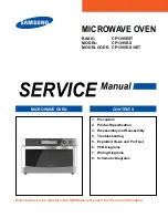
MICROWAVE OVEN

Refer to the service manual in the GSPN(see rear cover) for the more information.

1.  Precaution
2.  Product Specification
3.  Disassembly and Reassembly
4.  Troubleshooting
5.  Exploded Views and Part List
6.  PCB Diagrams
7.  Wiring Diagrams
8.  Schematic Diagrams

CONTENTS

MICROWAVE OVEN

BASIC:    

CP1395EST

MODEL:    

CP1395E-S

MODEL CODE:  CP1395E-S/XET

Summary of Contents for CP1395E-S

Page 1: ...or the more information 1 Precaution 2 Product Specification 3 Disassembly and Reassembly 4 Troubleshooting 5 Exploded Views and Part List 6 PCB Diagrams 7 Wiring Diagrams 8 Schematic Diagrams CONTENTS MICROWAVE OVEN BASIC CP1395EST MODEL CP1395E S MODEL CODE CP1395E S XET ...

Page 2: ...ement of Damper Motor Drive Motor 16 3 6 Replacement of Assy Weight Sensor 17 3 7 Calibration Method 18 3 8 Replacement of Heater 19 3 9 Replacement of Assy Duct Inner Gas sensor 20 3 10 Replacement of Control Circuit Board 22 4 Troubleshooting 23 4 1 Failure Codes 23 4 2 Part Checking method 26 4 3 Electrical Malfunction 28 5 Exploded Views and Parts List 41 5 1 Exploded Views 41 5 2 Main Parts L...

Page 3: ...ection within the microwave generating compartments check the magnetron wave guide or transmission line and cavity for proper alignment integrity and connections d Any defective or misadjusted components in the interlock monitor door seal and microwave generation and transmission systems shall be repaired replaced or adjusted by procedures described in this manual before the oven is released to th...

Page 4: ... repairing a MWO 11 To avoid any possible radiation hazard replace parts in accordance with the wiring diagram Also use only the exact replacements for the following parts Primary and secondary interlock switches interlock monitor switch 12 If the fuse is blown by the Interlock Monitor Switch Replace all of the following at the same time Primary door sensing switch and power relay as well as the I...

Page 5: ...n energized DO NOT measure the voltage in the high voltage circuit including filament voltage of magnetron PRECAUTION Never touch any circuit wiring with your hand nor with uninsulated tool during operation PRECAUTION Servicemen should remove their watches whenever working close to or replacing the magnetron 1 High Voltage Warning Do not attempt to measure any of the high voltages this includes th...

Page 6: ...ime Clean and Sanitary Steam Cleaning In the past cleaning your oven was difficult and labor intensive but you can keep your oven clean and sanitary using the steam cleaning function In addition you can also easily clean the inside of the upper grill by turning the upper grill a dual movable grill has been utilized so that you can use the oven as if new 2 2 Product Features Model CP1395E S Power c...

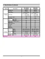
Page 7: ...erature Control Method Tact with Encoder dial Tact with Encoder dial Door Open Mechanism Drop Down Handle Drop Down Handle MW Distribution Mechanism T T T T Features Cooking Modes Microwave oven Yes Yes Grill Dual Grill Yes Yes Convection Fan Oven Yes Yes Speed Defrost Yes Yes Convection Top Heat Yes Yes Convection Heat Yes Yes Conventional Yes Yes Speed Cook Yes Yes Features Convection Temperatur...

Page 8: ...s Yes Carton Box Yellow Yellow Accessory Rack Oven Rack 1 1 Grill Insert No No Glass Tray 1 Baking Trays 2 Yes Yes Steam Clean Yes Yes Quick Guide Label No No Cook Book No No Coupler No No Barbeque No No Support Tray Yes Yes Physical Specification Dimension W x H x D Cavity 402 x 390 x 227 mm 402 x 390 x 227 mm Outside 520 x 403 x 453 5 mm 520 x 403 x 453 5 mm Shipping 618 x 466 x 550 mm 618 x 466...

Page 9: ...30A 1 TRAY OVEN DE97 00745C 1 ASSY WIRE RACK DE97 00136B 1 DE97 00136E 1 TRAY COOKING DE74 20002B 1 BOWL WATER DE75 00042F 1 DEFROST RACK DE63 00637A 1 SUPPORT TRAY DE94 02211A 1 ASSY STEAMER SUB DE94 01759B 1 PLATE STEAMER DE70 00565A 1 TRAY STEAMER DE63 00513A 1 ...

Page 10: ...Magnetron 1 Remove 3 screws from Air Cover 2 Remove 1 screw and Lead wire from magnetron 3 Remove nuts securing the magnetron to the wave guide Removal of Lamp 4 Remove 1 screw and wire lead 3 Disassembly and Reassembly 3 1 Replacement of Magnetron Lamp ...

Page 11: ...val of High Voltage Transformer 1 Discharge the high voltage capacitor 2 Disconnect all the leads 3 Take off the lead wire from guide air duct 4 Remove the mounting bolts 5 Lift up the assy guide air upper 3 2 Replacement of High Voltage Transfer ...

Page 12: ...emove their watches whenever working close to or replacing the magnetron PRECAUTION There exists HIGH VOLTAGE ELECTRICITY with high current capabilities in the circuits of the HIGHVOLTAGE TRANSFORMER secondary and filament terminals It is extremely dangerous to work on or near these circuits with the oven energized DO NOT measure the voltage in the high voltage circuit including filament voltage o...

Page 13: ...hoto Explaination Removal of guide air duct 1 Disconnect leads from vent motor 2 Take off the lead wire from guide air duct 3 Remove the mounting bolt 4 Lift up the assy guide air upper 3 3 Replacement of Assy Casing assembly ...

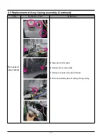
Page 14: ...laination Removal of assy casing 5 Disconnect all the leads 6 Remove the mounting bolts 7 Remove 2 screws in the cavity left side 8 Push the stumbling block for taking off assy casing 3 3 Replacement of Assy Casing assembly Continued ...

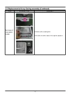
Page 15: ...s Explaination Photo Explaination Removal of convection motor 9 Remove the nut 10 Remove 4 screws from casing and washer plain 11 Take off the convection motor 3 3 Replacement of Assy Casing assembly Continued ...

Page 16: ...4 Parts Explaination Photo Explaination Removal of convection heater 12 Remove the mounting bolt 13 Pull the convection heater to the right to separate it 3 3 Replacement of Assy Casing assembly Continued ...

Page 17: ...o remove Door C Be careful when handling Door C because it is fragile Removal of Door E SCREW Door E Door E Ass y Door Sub Ass y Door Sub Following the procedure as shown in the figure insert and bend a thin metal plate between Door E and Door A until you hear the tick sound 1 Insertion depth of the thin metal plate should be 0 5mm or less Removal of Key Door Spring Key Door and Spring Key Door an...

Page 18: ... of the motor precisely for it to operate properly Removal of Drive motor 1 Take out the glass tray guide roller from oven cavity disconnect power 2 Remove turn table motor cover from case bottom CAUTION Remove sharp edge after cover removal 3 Disconnect leads from drive motor 4 Remove 2 screws to take off drive motor 5 Lift out the Drive motor 3 5 Replacement of Damper Motor Drive Motor ...

Page 19: ...guide roller from oven cavity disconnect power 2 Remove turn table motor cover from case bottom CAUTION Remove sharp edge after cover removal 3 Remove 5 screws from Assy weight sensor system 4 Lift out the Assy weight sensor system 3 6 Replacement of Assy Weight Sensor ...

Page 20: ... and weight button at the same time for 3 sec display shows tare and 0g 7 After you check 0g on the display Press keep warm 8 After you check 650g on the display Place 650g weight JIG on the glass tray middle Press keep warm button 650g setting 9 If it has no problem it appears YES on the display and beef then display is standby mode it s complete calibration But If it fails It appears Error on th...

Page 21: ... Parts Explaination Photo Explaination Removal of Heater 1 Remove 4 screws and wire lead 2 Pull the Heater in the direction of the groove from the inside the Cavity to separate it 3 8 Replacement of Heater ...

Page 22: ... Duct Inner Gas sensor Parts Explaination Photo Explaination Removal of guide air duct 1 Disconnect leads from vent motor 2 Take off the lead wire from guide air duct 3 Remove the mounting bolt 4 Lift up the assy guide air upper ...

Page 23: ...21 3 9 Replacement of Assy Duct Inner Gas sensor Parts Explaination Photo Explaination Removal of Assy duct inner Gas sensor 5 Disconnect leads from Main PCB 6 Remove 2 screws 7 Take off Assy duct inner ...

Page 24: ...nected Lead wire from Control box Assembly 2 Remove the 2 screws at both ends holding the Control Box Assembly 3 Pull the Control Box Assembly to the left to separate it 4 Remove 3 screws from PCB Assembly 5 Remove 10 screws from Assy Display 3 10 Replacement of Control Circuit Board ...

Page 25: ... model are excluded DEVICE ERROR CASE 0 Others 1 Open 1 Gas Sensor 2 Short 2 Temp Sensor 3 Weight Sensor 4 Easy PH Sensor 5 EEPROM Gas Sensor Error Code Case Solution Page E 11 GAS SENSOR OPEN In case the value of the gas sensor value is more than 210 during operation cancellation Check sensor part connection of sensor housing and PCB s connector 26 Page E 12 GAS SENSOR SHORT In case the value of ...

Page 26: ...230 DURING OPERATION OF MWO MODE In case the temperature rises over 230 during operation of mwo mode fire sensed 30 Page Weight Sensor Error Code Case Solution Page E 31 WEIGHT SENSOR OPEN In case the value of the weight sensor value is more than 999 during operation cancellation Check sensor 26 Page E 32 WEIGHT SENSOR SHORT In case the value of the weight sensor value is less than 30 during opera...

Page 27: ...his error occurs when communication does not working between MCU and LCD display MCU under operation Check the communication about Assy display and main PCB 33 Page Others Error Code Case Solution Page E A1 DAMPER S W In case it fails to sense the DAMPER to open or close for 1minutes Check Damper motor 34 Page SE Key short Error 10 seconds Turn off set and restart 35 Page 4 1 Failure Codes Continu...

Page 28: ...Ω 100 MΩ exceed T C O 0 1 1 Ω 100 MΩ exceed Damper Motor 13 5 15 5 kΩ 100 MΩ exceed H V Trans Primary 1 5 Ω Secondary 110 200 Ω 100 MΩ exceed Convection Motor 120 150 Ω 100 MΩ exceed Convection Heater 120 150 Ω 100 MΩ exceed 4 2 Part Checking method ...

Page 29: ... 27 Parts Photo Good No Good T T Motor 13 5 17 kΩ 100 MΩ exceed Fan Motor 50 60 Ω 100 MΩ exceed Grill Heater 60 80 Ω 100 MΩ exceed 4 2 Part Checking method Continued ...

Page 30: ...r wire connected properly Does the voltage change as the humidity temperature and weight change Replace the sensor Check if the sensor wire is damaged if the housing is loose and if the sensor and the wire are properly connected Check if the voltage of the GND and sensor changes using a digital multi meter by forcefully changing the humidity temperature and weight Connect the sensor Connect the wi...

Page 31: ...mperature and weight Check if the sensor and related parts such as the connector or soldering parts are slightly shorted Remove the shorted part of the temperature sensor Remove any foreign Substance from the shorted part YES NO YES YES NO NO YES NO Sensor Short Error E 12 E 22 E 32 Is the sensor shorted The sensor is out of order Replace the sensor Perform the operation again and check if it is w...

Page 32: ...ng as an obstacle in front of the sensor Does it heat with completely dried food Replace the sensor If the sensor is contaminated by a foreign substance it may fail to detect the humidity Since heating completely dried food may burn the food take care Insert food and heat it again Place food with moisture into it and heat it again Remove the an foreign substance or obstacle Does it heat up without...

Page 33: ...to a few MΩ Preheating Error E 23 Is the heater temperature very low Is the temperature sensor connected properly Is the resistance between the heater terminals more then a few MΩ Check the heater related drive part Replace the heater 230V is normal Reconnect the temperature sensor properly Replace the heater Does the heater work S W Error After Power On does the symptom continue Replace the PCB P...

Page 34: ...again and check if it is working properly Is the oven in MW mode Is the internal temperature over 200 degrees Is the sensor connectivity normal An E 25 error occurred Press the Cancel key Connect it properly and try again After Power On does the symptom continue Press the Cancel key to cancel the current state Perform the calibration Refer to page 18 4 3 5 E 25 ...

Page 35: ...able over the support tray properly Perform the calibration Refer to page 18 Perform the calibration Refer to page 18 Replace the PCB Replace the assy weight sensor Perform the operation again and check it is working properly Do you have same problem S W Error Perform the operation again and check it is working properly Doyou have same problem YES 4 3 6 E 37 E 38 E 39 ...

Page 36: ...S NO NO EEPROM이 삽입 되었는가 S W 오동작 YES YES YES NO E 51 E 53 is displayed Has the EEPROM been inserted Is the EEPROM terminal opened or is there a short circuit EEPROM Defect Replace the EEPROM Does it work properly Perform the operation again and check if it is working properly S W Error After Power On does the symptom continue Replace the PCB Perform the calibration Refer to page 18 4 3 7 E 51 E 53 ...

Page 37: ...o assy display Remove any foeign substance from the shorted part Remove any foeign substance from the shorted part Replace the PCB Perform the operation again and check if it is working properly Does main PCB disconnect to assy display Is the display connector CN01 part of the display PCB shorted Is the connector CN201 part of the main PCB shorted Perform the calibration Refer to page 18 4 3 8 E 8...

Page 38: ...roperly connected S W Error The Micro Switch is defective Replace the Micro Switch Connect the Micro Switch properly The voltage between the two terminals while operating 230V is normal The resistance of the Motor Approximately 15K is normal Check if the terminal has been inserted After Power On does the symptom continue Replace the PCB Perform the operation again and check if it is working proper...

Page 39: ... is working properly S W Error Is a specific key not recognized Is the key recognized intermittently The membrane is defective Replace the Control Panel Is the key not recognized at all After Power On does the symptom continue Replace the PCB Perform the calibration Refer to page 18 4 3 10 SE ...

Page 40: ...rks after appropriate parts are replaced Replace appropriate parts Replace ASSY PCB Replace H V DIODE H V Capacitor H V Trans and Magnetron Is the power part of PCB normal Are high voltage circuits normal Normal Operation resistance PCB Input 230V is Normal Caution 1 Be careful of high voltage circuits 2 Discharge a high voltage capacitor Make sure inspect the power relay after priry interlock swi...

Page 41: ...rts Replace Control Relay Replace TCO Replace HEATER Replace MOTOR Replace DAMPER Caution 1 Be careful not to touch a heater because it is hot 2 Do not touch the leads after repair because it is hot Check whether parts normally work after replaced Check whether it normally works after Control Relay is replaced Check whether it normally works after appropriate parts are replaced Make sure inspect t...

Page 42: ... replaced Check whether it normally works after appropriate parts are replaced Check whether it normally works after Main Display are replaced Check connector Replace Buttons Replace Ass y display Replace a dial Are buttons a dial display normal Is the Flat wire properly connected Flat wire No 1 7 5V is normal Normal Operation Make sure inspect the power relay after replacing primary interlock swi...

Page 43: ...M511 P403 H092 P259 M174 M075 B048 B045 B023 B013 B025 H067 M054 M187 M237 T173 T174 P059 M090 H003 H006 H015 H014 M446 H008 H001 M436 M384 B061 B062 B046 B058 B022 M008 M049 M051 X020 M047 M155 M046 M131 M048 M007 T079 W036 P179 T001 T007 P426 P429 T058 T009 T124 T116 T010 T030 M516 T116 T172 W038 W042 T170 T171 P435 X013 X017 X023 5 Exploded Views and Parts List 5 1 Exploded Views ...

Page 44: ...US SECC T0 6 TURN TA 1 SA H067 DE94 02210A ASSY CASING CP1370 CPS1390 TRIO PLUS L 1 SA H091 DE61 00973A STOPPER GRILL HEATER L AURORA SECC T0 8 1 SNA H092 DE61 00974A STOPPER GRILL HEATER R AURORA SECC T0 8 1 SNA M001 DE64 02317H PANEL OUTER TRIO PLUS EGI SECC T0 6 W520 1 SA M003 DE61 01274A BRACKET UPPER CP1370 EGI SECC T1 0 TRIO 1 SNA M005 DE61 70060A SPRING PLATE SK 5 T0 5 2 SA M007 DE47 00045D...

Page 45: ...T NT 101 250V 10A 125V 15A 1 SA M511 DE67 00257A DUCT INNER CP1370 EGI SECC T0 5 TRIO PLU 1 SA M516 DE96 00837A ASSY SENSOR WEIGHT SYSTEM CP1370 WEIGHT 1 SA M527 DE59 00002A DIODE H V MWO ALL 2CL4512H 450mA 13KV 1 SA M533 DE61 01030A SUPPORT HEATER AURORA ALUMINA T12 IV 2 SA P059 DE63 00481A COVER FRONT AURORA PROJECT PP TB53 1 SA P083 DE72 00040B DAMPER PIN AURORA PROJECT MSWR PI 2 AURO 1 SA P166...

Page 46: ...R10 D268 H35 SNC2 1 SA T170 DE63 00637A TRAY DEFROST TRIO PLUS ABS 78268 LIGHT 1 SA T171 DE61 01237A SUPPORT TRAY TRIO PLUS WEIGHT SENSOR ALC 1 SA T172 DE97 00750A ASSY TRAY COOKING CP1370 DECAL FILM PRIN 1 SA T173 DE75 00076A RACK L Trio plus MSWR T4 W24 75 L310 25 1 SA T174 DE75 00077A RACK R Trio plus MSWR T4 W24 75 L310 25 1 SA W002 DE96 00814C ASSY WIRE HARNESS A CP1395EST 230V 50HZ 1 SNA W03...

Page 47: ...RY SI 1 SA D049 DE94 02194A ASSY DOOR TRIO PLUS PC 141R VICTORY SILV 1 SA D097 DE66 00190A SHAFT HINGE FQ159ST SUM24L 2 SA D098 DE61 01254A SPRING ETC HINGE R TRIO PLUS PWB SWPB P 1 SA D099 DE61 01253A SPRING ETC HINGE L TRIO PLUS PWB SWPB P 1 SA D147 DE63 00626A COVER HANDLE TRIO PLUS ABS VICTORY SILVE 1 SA D149 DE64 02344A KEY SPRING CP1370 PWA SWPA BLACK TRIO PL 2 SA D157 DE61 01248A BRACKET KE...

Page 48: ...R 1 SA C071 DE63 00635A COVER LED TRIO PLUS ABS T2 0 WHT LDW68 1 SA C082 DE94 02192F ASSY CONTROL BOX CP1395E S XEF 230V50HZ 1 SNA C154 DE96 00839A ASSY DISPLAY CP1395EST DAM ATLCD 00 WHIT 1 SNA C161 DE64 02312C KNOB DIAL L CPS1390EST ABS BLACK TRIO P 1 SA C162 DE64 02311A KNOB DIAL R TRIO PLUS ABS BLACK TURN TA 1 SNA C325 DE94 02217E ASSY KNOB L CP1395 ABS LED BLK VICTORY 1 SNA C326 DE94 02218A A...

Page 49: ...60 30016A NUT FLANGE MSWR10 3 SA 1 2 6006 001174 SCREW TAPPING TH WE 2S M4 L12 ZPC WHT 4 SA 1 2 6002 000630 SCREW TAPPING PH 2S M3 L8 ZPC WHT S 12 SNA 1 3 6002 000630 SCREW TAPPING PH 2S M3 L8 ZPC WHT S 5 SNA 1 2 6002 000630 SCREW TAPPING PH 2S M3 L8 ZPC WHT S 6 SNA 1 3 6002 000234 SCREW TAPPING TH NO 2S M4 L16 ZPC WHT 2 SNA 1 3 6003 000115 SCREW TAPTYPE BH B M3 L6 ZPC BLK SWRC 2 SNA 1 2 6002 0013...

Page 50: ... Control 14 CN201 Display Module Connector A Terminal for Connecting with Display Module 15 CN202 On Board Writing Connector When do micom revision connect to micom writer No connection at normal times 16 CN501 Door switch Damper Humidity Sensing Connector A Terminal for Connecting with Door Switch Damper switch Temperature Sensor 17 CN601 Relay Connector A Terminal for Connecting with Relay Conta...

Page 51: ...R NEUTRAL AC220V 2 NO PIN 3 AC POWER LIVE AC220V 4 NO PIN 5 LIVE CONTROL 6 NO PIN 7 CONV MOTOR RELAY CN703 1 GAS SENSOR S1 2 GAS SENSOR S2 3 GAS SENSOR H1 4 GAS SENSOR H2 RY603 1 POWER APPLY POWER TO HVT RELAY 1 2 POWER APPLY POWER TO HVT RELAY 1 RY610 1 GRILL HEATER RELAY 1 2 GRILL HEATER RELAY 2 RY611 1 STEAM HEATER RELAY 1 2 STEAM HEATER RELAY 2 CN603 1 WATER PUMP RELAY 2 NO PIN 3 POWER 0V GND ...

Page 52: ... 50 7 Wiring Diagram 7 1 Wiring Diagram ...

Page 53: ... 51 8 Schematic Diagram 8 1 Schematic Diagram ...

Page 54: ...law GSPN Global Service Partner Network Contry Web Site North America service samsungportal com Latin America latin samsungportal com CIS cis samsungportal com Europe europe samsungportal com China china samsungportal com Asia asia samsungportal com Mideast Africa mea samsungportal com Samsung Electronics Co Ltd July 2010 Printed in Korea Code No DE68 05878A ...

Reviews: