Disassembly & Reassembly
12-2
Samsung Electronics
Part Name
Description
Description Photo
Chassis
Holder
①
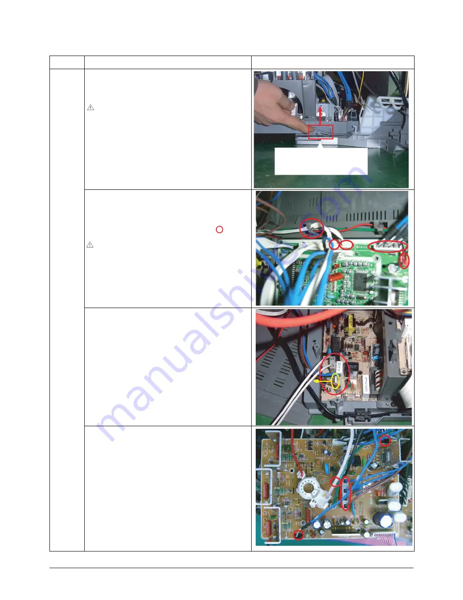
Separate the Ass'y Holder chassis from the Front Cabinet.
②
Pull the Chassis Holder lifting the fixing clip up.
Notice: Pulling the Chassis Holder by force may damage the
clip or the connector. Pull the Chassis Holder just until the clip
comes off the hole.
①
Separate the Speakers, the Side AV Wire, the Side Control,
and the Remote Control Sensor Cable from the Front Cabinet
and the System Board.
②
Separate the wire from the Wire fixing holder at .
Notice: Since there is a clip to connect the Connector Header
in the Wire Connector, pulling it by force may damage the clip or
the connector. Press the clip down completely and pull the con-
nector.
①
Separate the D-Coil and power cable from the Front Cabinet
and Power Board.
②
To separate the power cord, slide the fixing clip and lift the
cable up.
①
Separate the CRT Ass'y from the CRT
②
Separate the TBC wire, GND, VM and Tilt cables from the
CRT Ass'y sequentially.
Pull the chassis while raising the
clip fixing the Front Cabinet and
the Holder Chassis.
12-1-2 Disassembling the CRT and Chassis
Summary of Contents for CS-29Z30SPQ
Page 10: ...1 6 Samsung Electronics MEMO ...
Page 18: ...Alignment Adjustment 3 4 Samsung Electronics ...
Page 67: ...MEMO Samsung Electronics 5 24 ...
Page 87: ...7 6 Samsung Electronics MEMO ...
Page 119: ...12 6 Samsung Electronics MEMO ...


