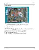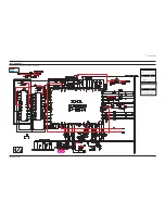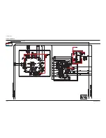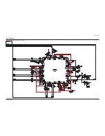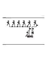
PCB Diagram
9-8
Samsung Electronics
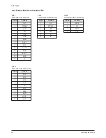
9-4-3 CRT Board Connector Pin
CNC01
Connects the R/G/B signal from the System Board
CNC02
Connects the power from the Deflection Board
FV1
Connects the VM signal to the DY Ass'y
FN1
Connects the signal to the Tilt Coil
PIN No.
Pin Name
1
IK
2
GND
3
B
4
GND
5
G
6
GND
7
R
8
GND
9
15V
10
VM
11
PWR
12
TLT
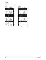
PIN No.
Pin Name
1
VCC-200V
2
NC
3
HEATER
4
VCC_-16.5V
5
VCC_20V
6
GND
7
NC
8
ABL
9
NC
10
VCC_142V
11
12
PIN No.
Pin Name
1
VM
2
NC
3
VM
PIN No.
Pin Name
1
GND
2
GND
3
TILT
4
TILT
Summary of Contents for CS-29Z30SPQ
Page 10: ...1 6 Samsung Electronics MEMO ...
Page 18: ...Alignment Adjustment 3 4 Samsung Electronics ...
Page 67: ...MEMO Samsung Electronics 5 24 ...
Page 87: ...7 6 Samsung Electronics MEMO ...
Page 119: ...12 6 Samsung Electronics MEMO ...


