

COLOR TELEVISION RECEIVER
Chassis :
KS1A(P)_Rev.2
Model :
CS14Y530X/BWT
CS14Y510X/BWT
CS14H40X/BWT,CS14H40S/ATG
CS21D90X/BWT
CS14V5MJ0X/CBM
COLOR TELEVISION RECEIVER
CONTENTS
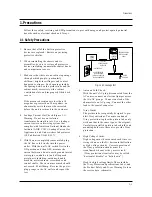
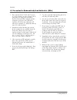
Precautions
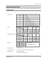
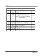
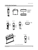
Specifications and IC Data
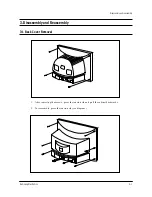
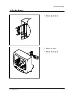
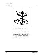
Disassembly and Reassembly
Alignment and Adjustment
Troubleshooting
Exploded View and Parts List
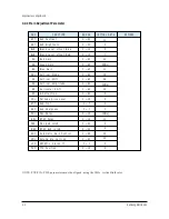
Electrical Parts List
Block Diagram
Wiring Diagram
Schematic Diagrams
1.
2.
3.
4.
5.
6.
7.
8.
9.
10.
Summary of Contents for CS14Y530X/BWT
Page 10: ...2 4 MEMO ...
Page 52: ...Electrical Parts List 7 22 Samsung Electronics MEMO ...
Page 55: ...9 2 MEMO ...
Page 58: ...Samsung Electronics Schematic Diagrams 10 3 TP15 TP16 10 2 A V RCA SW SUB ASSY TP15 TP16 ...
Page 59: ...10 4 Schematic Diagrams Samsung Electronics TP15 TP16 TP15 TP16 10 3 A V SCART SW SUB ASSY ...


