background image

1-1 Safety Precautions  (Continued)

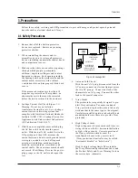
9. High voltage is maintained within specified

limits by close-tolerance, safety-related 
components and adjustments.  If the high 
voltage exceeds the specified limits, check
each of the special components. 

10. Design Alteration Warning:

Never alter or add to the mechanical or 
electrical design of this unit. Example: Do not
add auxiliary audio or video connectors. Such
alterations might create a safety hazard. Also,
any design changes or additions will void the
manufacturer’s warranty.

11. Hot Chassis Warning:

Some TV receiver chassis are electrically 
connected directly to one conductor of the AC
power cord. If an isolation transformer is not
used, these units may be safely serviced only
if the AC power plug is inserted so that the
chassis is connected to the ground side of the
AC source.  

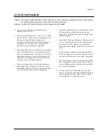
To confirm that the AC power plug is inserted 
correctly, do the following: Using an AC 
voltmeter, measure the voltage between the 
chassis and a known earth ground. If the 
reading is greater than 1.0V, remove the AC
power plug, reverse its polarity and reinsert.
Re-measure the voltage between the chassis
and ground. 

12. Some TV chassis are designed to operate with

85 volts AC between chassis and ground,
regardless of the AC plug polarity. These units
can be safely serviced only if an isolation
transformer inserted between the receiver and
the power source. 

13. Some TV chassis have a secondary ground

system in addition to the main chassis ground.
This secondary ground system is not 
isolated from the AC power line. The two
ground  systems are  electrically separated by
insulating material that must not be defeated
or altered.

14. Components, parts and wiring that appear to

have overheated or that are otherwise 
damaged should be replaced with parts that
meet the original specifications.  Always 
determine the cause of damage or overheat-
ing, and correct any potential hazards.

15. Observe the original lead dress, especially

near the following areas:  Antenna wiring,
sharp edges, and especially the AC and high
voltage power supplies.  Always inspect for
pinched, out-of-place, or frayed wiring.   Do
not change the spacing between components
and the printed circuit board.  Check the AC
power cord for damage.  Make sure that leads
and components do not touch thermally hot
parts. 

16. Picture Tube Implosion Warning:

The picture tube in this receiver employs
“integral implosion” protection.  To ensure
continued implosion protection, make sure
that the replacement picture tube is the same
as the original.

17. Do not remove, install or handle the picture

tube  without first putting on shatterproof
goggles equipped with side  shields.  Never
handle the picture tube by its neck.   Some 
“in-line” picture tubes are equipped with a 
permanently attached deflection yoke; do not
try to remove such “permanently attached”
yokes from the picture tube.

18. Product  Safety Notice: 

Some electrical and mechanical parts have
special safety-related characteristics which
might not be obvious from visual inspection.
These safety features and the protection they
give might be lost if the replacement compo-
nent differs from the original—even if the
replacement is rated for higher voltage,
wattage, etc.  

Components that are critical for safety are
indicated in the circuit diagram by shading,  
(      ) or (      ). 

Use replacement components that have the

same ratings, especially for flame resistance
and dielectric strength specifications. 
A replacement part that does not have the
same safety characteristics as the original
might create shock, fire or other hazards. 

Precautions

1-2

Samsung Electronics

!

Summary of Contents for CS21K9MAZX/XST

Page 1: ...TELEVISION RECEIVER CONTENTS Precautions Specifications and IC Data Disassembly and Reassembly Alignment and Adjustment Troubleshooting Exploded View and Parts List Electrical Parts List Block Diagram Wiring Diagram Schematic Diagrams 1 2 3 4 5 6 7 8 9 10 SERVICE Manual ...

Page 2: ...dle brackets metal cabinets screwheads and control shafts The current measured should not exceed 0 5 milliamp Reverse the power plug prongs in the AC outlet and repeat the test Fig 1 1 AC Leakage Test 6 Antenna Cold Check With the unit s AC plug disconnected from the AC source connect an electrical jumper across the two AC prongs Connect one lead of the ohmmeter to an AC prong Connect the other le...

Page 3: ...t appear to have overheated or that are otherwise damaged should be replaced with parts that meet the original specifications Always determine the cause of damage or overheat ing and correct any potential hazards 15 Observe the original lead dress especially near the following areas Antenna wiring sharp edges and especially the AC and high voltage power supplies Always inspect for pinched out of p...

Page 4: ...g and accessible conductive parts examples metal panels input terminals and earphone jacks 6 Insulation Checking Procedure Disconnect the power cord from the AC source and turn the power switch ON Connect an insulation resistance meter 500V to the blades of the AC plug The insulation resistance between each blade of the AC plug and accessible conductive parts see above should be greater than 1 meg...

Page 5: ...trical charges that damage ESDs 5 Use only a grounded tip soldering iron when soldering or unsoldering ESDs 6 Use only an anti static solder removal device Many solder removal devices are not rated as anti static these can accumulate sufficient electrical charge to damage ESDs 7 Do not remove a replacement ESD from its protective package until you are ready to install it Most replacement ESDs are ...

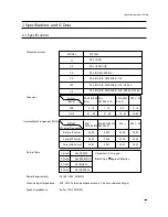
Page 6: ...uency Picture IF Carrier Sound IF Carrier Color Sub Carrier PAL SECAM D K 1 13 21 69 PAL SECAM D K SECAM K1 38 90 32 40 34 47 SECAM K1 PAL D 2 9 13 57 PAL I 38 90 32 90 34 47 MODEL CI CII CX CK CW CS 14 Inch 20 Inch 21 Inch AC 160 300V 50 60Hz VHF UHF Telescopic dipole antenna 75 ohm unbalanced type 8 ohm 7W 7W MAX SYSTEM PAL I UHF PAL I VHF UHF PAL B G SECAM B G PAL B G D K SECAM B G D K PAL B G ...

Page 7: ...108 LTV817B PHOTO COUPLER SPM802ER TTX English Croatian Romanian Hungarian Polish Czech Bulgarian Russian Portugal IC201S Philips Philips SPM802ERN W O TTX English Croatian Romanian Hungarian Polish Czech Bulgarian Russian Portugal VERTICAL OUTPUT LA7840 TDA7266S IC301 IC601 SOUND AMP 3W x 1CH or 3W x 2CH or 5W x 2CH IC801S KA5Q0765R POWER IC STR IC802 KA7632 CUSTOM REGULATOR 5V 8V 3 3V IC101 U446...

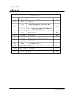
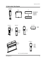
Page 8: ...64 SPM 802ER Pin 64 X24CO8P Pin 8 KS24C080 Pin 8 U4468B Pin 16 IC TRANSISTOR LA7840 TDA6107Q KA7632 TRANSISTOR TRANSISTOR 2SD1651 2SD1650 2SD2499 KSA614 B C E E B C KSC815 Y KSA539 Y BC548 KTC9014 IC UPC574J or KA33V SAW FILTER E C B KSR1012 KSR1010 KSR2010 KTD863 Y KSC2331 Y 1 1 1 G3956M K9260M Fig 2 1 Semiconductor Base Diagrams ...

Page 9: ...2 4 MEMO ...

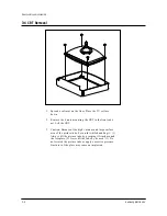
Page 10: ...ics 3 1 Disassembly and reassembly 3 Disassembly and Reassembly 3 1 Back Cover Removal 1 After removing the screws press the tension rib and pull the cabinet backwards 2 To reassemble press the tension rib see diagram ...

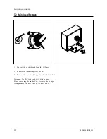
Page 11: ...Separate the socket board from the CRT neck 2 Remove the Anode Cap from the CRT 3 Remove the main board by pulling it with both hands Warning The FBT is charged with high voltage Before removing the Anode Cap discharge the voltage through one of the heat sinks on the main board ...

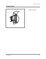
Page 12: ...3 3 Speaker Removal Disassembly and reassembly Samsung Electronics 3 3 1 Remove the speaker by pressing the tension rib ...

Page 13: ...RT to the front cabi net Lift the CRT 3 Caution Because of the high vacuum and large surface area of the picture tube be careful while handling it 1 Always lift the picture tube by grasping it firmly around the faceplate 2 Never lift the tube by its neck 3 Do not scratch the picture tube or apply excessive pressure Fractures of the glass may cause an implosion ...

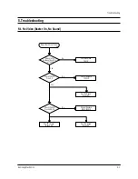
Page 14: ... On No Sound Yes No Open the IF Pin of Tuner Check Replace TU01S No Measure the Voltage of Each Pin of TU01S Check IC201S Pins 2 3 See No Video Sound OK See No Sound Video OK Check Replace IC201S Yes No Check Replace IC501 IC201S Check IC201S Pins 40 49 50 See No Sound Video OK ...

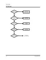
Page 15: ...B Lines Check IC802 Pin 8 8V Pin 9 9V Pin 10 5V Check Replace IC801S D801S D802S D803S D804S FP801S Check Replace IC802 KA7632 Check IC201S Pin 1 Stand by 0V Normal 3 3V Check Replace IC201S Check IC201S Pin 1 3 3V Check Replace IC201S µ com Check IC201S Pin 33 H out Check Replace IC201S Q401 Q402 ...

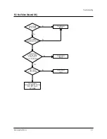
Page 16: ...No No Check IC201S Pin 40 CVBS Check Replace IC201S Check IC201S Pins 38 R214 R215 Check IC201S Pin 49 V GUARD Pin 50 Cut off Pin 51 53 R G B out Check Replace IC201S Check IC501 on the CRT PCB Check Replace IC501 Check Replace R421 R505 HEATER 6 3Vrms D503 CRT G1 pin CRT V999S ...

Page 17: ... V Front assembly Check IC201S Pin 44 Sound Out Check Replace IC201S Check IC601 Pin 3 13 B 10 12 5V Check Replace Q904 IC201S Check IC601 Check Replace IC601 Check IC601 Pins 6 0V Check Replace R814 R815 Yes Yes No Yes Yes 5 5 No TTX No See No Video Check IC201S Check Replace IC201S Yes ...

Page 18: ... 04043A KNOB CONTROL 21K9 TSE ABS HB G3676 SVM3 1 S N A T0057 AA64 70123A BADGE BRAND NEW AL L50 FLAT SILVER SAMSU 1 S N A T0175 AA96 01178A ASSY SPEAKER P 8OHM 3001 001037 AA39 205 1 S N A T0015 AA64 04038B CABINET BACK 21K9 245 TSE FV2 GR503 1 T0527 AA65 00009B CLAMPER CORE D COIL 21A8 NYLON 66 V0 4 S N A T0063 AA03 00403A CRT COLOR A51QDX993X 0MG 1 75MH 18MH 3 1 1 T0066 AA96 20112C ASSY POWER C...

Page 19: ...DIODE RECTIFIER FMG G2CS 1000V 3A DO 41 3 T0083 0402 001599 DIODE RECTIFIER DGP30L 1500 3A DO 201AD 3 T0090 0502 001160 TR POWER 2SD2499 NPN 50000mW TO 3P BK 8 3 PC801S 0604 001032 PHOTO COUPLER TR 170 260 300mW DIP 4 ST 3 IC112 1103 001106 IC EEPROM 24C080 1Kx8Bit DIP 8P 9 6x6 4m 3 T0900 1404 001045 THERMISTOR NTC 4 7ohm 15 2900K 35 0mW T 3 P803T 1404 001265 THERMISTOR PTC 4 5OHM 100OHM 30 20 22 ...

Page 20: ...ITCHING 1N4148 75V 150MA DO 35 T 4 CISS 0401 000005 DIODE SWITCHING 1N4148 75V 150MA DO 35 T 4 CISS 0401 000005 DIODE SWITCHING 1N4148 75V 150MA DO 35 T 4 CISS 0401 000005 DIODE SWITCHING 1N4148 75V 150MA DO 35 T 4 CISS 0401 000005 DIODE SWITCHING 1N4148 75V 150MA DO 35 T 4 T0083 0402 000132 DIODE RECTIFIER 1N4004 400V 1A DO 41 TP 4 T0083 0402 000132 DIODE RECTIFIER 1N4004 400V 1A DO 41 TP 4 T0083...

Page 21: ...3 2MM 4 R125 2001 000739 R CARBON 4 7MOHM 5 1 8W AA TP 1 8X3 2MM 4 R125 2001 000739 R CARBON 4 7MOHM 5 1 8W AA TP 1 8X3 2MM 4 R125 2001 000786 R CARBON 47KOHM 5 1 8W AA TP 1 8X3 2MM 4 R125 2001 000793 R CARBON 47OHM 5 1 8W AA TP 1 8X3 2MM 4 R125 2001 000793 R CARBON 47OHM 5 1 8W AA TP 1 8X3 2MM 4 R125 2001 000857 R CARBON 560OHM 5 1 8W AA TP 1 8X3 2MM 4 R125 2001 000857 R CARBON 560OHM 5 1 8W AA T...

Page 22: ... 2401 000603 C AL 1UF 20 50V GP TP 5X11 2 4 C701 2401 000660 C AL 2 2uF 20 50V GP TP 5x11 5 4 C701 2401 000660 C AL 2 2uF 20 50V GP TP 5x11 5 4 C701 2401 000660 C AL 2 2uF 20 50V GP TP 5x11 5 4 C701 2401 000722 C AL 2200uF 20 25V WT TP 16x25 7 5 4 C701 2401 000758 C AL 0 22UF 20 50V GP TP 5X11 5 4 C701 2401 000962 C AL 22uF 20 50V GP TP 5x11 5 4 C701 2401 001101 C AL 330uF 20 16V GP TP 8x11 5 5 4 ...

Page 23: ...SN BSP3 1 2H S N A 4 EY827 6042 000002 EYELET ID1 5 OD2 L2 8 NI SN BSP3 1 2H S N A 4 EY828 6042 000002 EYELET ID1 5 OD2 L2 8 NI SN BSP3 1 2H S N A 4 EY829 6042 000002 EYELET ID1 5 OD2 L2 8 NI SN BSP3 1 2H S N A 4 EY830 6042 000002 EYELET ID1 5 OD2 L2 8 NI SN BSP3 1 2H S N A 4 EY833 6042 000002 EYELET ID1 5 OD2 L2 8 NI SN BSP3 1 2H S N A 4 EY850 6042 000002 EYELET ID1 5 OD2 L2 8 NI SN BSP3 1 2H S N...

Page 24: ...Electrical Parts List 7 6 Samsung Electronics MEMO ...

Page 25: ...R AUDIO AMP 7W 2CH FBT S W TRANS AC DC Converter SMPS CONT ROLER KA7632 14N 21F CRT VIDEO AMP TDA6107 A 125V A 13V To FBT B To Sound AMP B UOC UOC RGB V Drive H Drive Pre AMP VIF SAW S W B 8V B 5V A 3 3V TUNER Back JACK RCA In Out OPTION SIF S W SIF IC MSP Option OPTION 180V 16 5V IF A V IN A V OUT OPTION MONO ...

Page 26: ...SOUND L OUT SOUND L IN SOUND R IN FRONT AUDIO IN GND 21 PIN AUDIO IN GND CRT PCB POWER CORD 1 2 3 4 5 180V GND CUT OFF B OUT G OUT R OUT HEAT NC 1 2 3 GND HEAT 180V 1 2 3 4 L OUT R OUT L OUT R OUT CN501B CN501 CN603 CN701 9 10 11 SOUND R OUT GND FRONT VIDEO IN 21 PIN VIDEO IN 6 7 8 ...

Page 27: ...9 2 MEMO ...

Page 28: ...s 10 1 Samsung Electronics 10 Schematic Diagrams 10 1 ONECHIP MICOM Power Line TP01 TP02 TP04 TP05 TP07 TP08 TP10 TP11 TP13 TP14 TP03 TP06 TP09 TP12 TP03 TP05 TP04 TP06 TP12 TP13 TP09 TP08 TP10 TP11 TP02 TP07 TP14 TP01 ...

Page 29: ...Schematic Diagrams 10 2 Samsung Electronics 10 2 SOUND EXT A V SCART Power Line ...

Page 30: ...Schematic Diagrams 10 3 Samsung Electronics 10 3 SOUND EXT A V RCA Power Line ...

Page 31: ...Schematic Diagrams 10 4 Samsung Electronics 10 4 POWER CRT VERTICAL HORIZONTAL TP01 TP02 TP03 TP04 TP05 TP06 Power Line TP06 TP05 TP04 TP03 TP02 TP01 ...

Page 32: ...Schematic Diagrams 10 5 Samsung Electronics 10 5 SUB PCB MONO ...

Page 33: ...Schematic Diagrams 10 6 Samsung Electronics 10 6 SUB PCB STEREO ...

Page 34: ...g Electronics Co Ltd Jul 2004 Printed in Korea AA82 01964A This Service Manual is a property of Samsung Electronics Co Ltd Any unauthorized use of Manual can be punished under applicable International and or domestic law ...

Reviews: