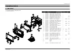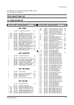
Alignment and Adjustments
1-8
Samsung Electronics
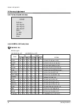
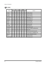
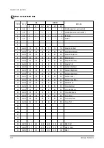
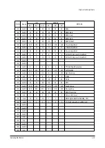
ITEMS
R-Cutoff
G-Cutoff
B-Cutoff
Color on/off
CR offset
CB offset
R-Drive
G-Drive
B-Drive
Sub-Bright
Sub-Contrast
Sub-Color
Sub-Tint
CTI-Level
COL AXIS
LTI-Level
VSU
Merody Volume
29"
32
25
32
1
32
32
32
32
32
40
7
15
28
2
1
1
2
7
32"
32
25
32
1
32
32
32
32
32
30
7
15
28
2
1
1
2
7
34"
32
25
32
1
32
32
32
32
32
30
7
15
28
2
1
1
2
7
29"
25
25
25
1
31
30
37
32
32
19
7
15
28
1
1
1
2
4
28"
25
25
25
1
31
30
37
32
32
19
7
15
28
1
1
1
2
4
32"
41
32
38
1
32
32
40
32
38
47
7
15
28
1
1
1
2
7
REMARK
R-cutoff control adj
G-cutoff control adj
B-cutoff control adj
Initial Value : "0"--> 1
DC-offset canceling
DC-offset canceling
R-Drive control adj
G-Drive control adj
B-Drive control adj
Sub-Bright control
Sub-Contrast control
color gain control(PAL SETTING AGAIN)
HUE control
Chrominance Transient Improvement
color detection axis setting(NTSC/USA)
Luminance Transient Improvement
vertical osd position
Volume gain control
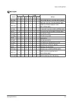
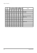
Video Adjust 1
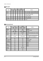
CIS
EUROPE
Summary of Contents for CS29A11SSGXBWT
Page 2: ...ELECTRONICS Samsung Electronics Co Ltd Mar 2003 Printed in Korea AA82 00369A ...
Page 18: ...1 16 Samsung Electronics MEMO ...
Page 35: ...5 2 MAIN 2 4 2 Schematic Diagrams Samsung Electronics TP12 TP13 TP18 TP15 TP14 TP16 TP17 ...
Page 36: ...Samsung Electronics Schematic Diagrams 4 3 5 3 MAIN 3 TP19 TP20 TP21 TP22 TP23 TP24 ...
Page 37: ...4 4 Schematic Diagrams Samsung Electronics 5 4 MAIN 4 TP25 ...
Page 39: ...4 6 Schematic Diagrams Samsung Electronics 5 5 MICOM ...
Page 40: ...Samsung Electronics Schematic Diagrams 4 7 5 6 CRT ...
Page 41: ...4 8 Schematic Diagrams Samsung Electronics 5 7 F BOX 1 ...
Page 42: ...Samsung Electronics Schematic Diagrams 4 9 5 8 F BOX 2 ...
Page 43: ...4 10 Schematic Diagrams Samsung Electronics 5 10 A V SIDE 5 12 CONTROL 5 11 LED ...


