


COLOR TELEVISION RECEIVER
Chassis :
KS3A (REV. 1)
Model:
CS29A5WT8X/XSG
CS29A6WT8X/BWT
COLOR TELEVISION RECEIVER
CONTENTS
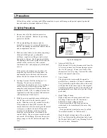
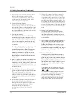
Precautions
Reference Information
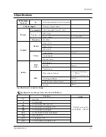
Specifications
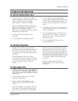
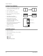
Alignment and Adjustments
Troubleshooting
Exploded Views and Parts List
Electrical Parts List
Block Diagrams
Wiring Diagram
Schematic Diagrams
1.
2.
3.
4.
5.
6.
7.
8.
9.
10.
Summary of Contents for CS29A5WT8X/XSG
Page 11: ...2 6 Samsung Electronics MEMO ...
Page 13: ...3 2 Samsung Electronics MEMO ...
Page 31: ...MEMO 5 4 Samsung Electronics ...
Page 48: ...8 Block Diagrams Samsung Electronics Schematic Diagrams 8 1 8 1 Power Diagram ...
Page 49: ...8 2 Block Diagram Schematic Diagrams 8 2 Samsung Electronics ...
Page 51: ...9 2 Samsung Electronics MEMO ...
Page 56: ...10 5 PIP Samsung Electronics Schematic Diagrams 10 5 Power Line Si l Li ...
Page 57: ...Schematic Diagrams 10 6 Samsung Electronics 10 6 CRT SWITCH SWITCH CRT Power Line Signal Line ...
Page 58: ...ELECTRONICS Samsung Electronics Co Ltd AUG 2000 Printed in Korea 3KS3A 2933 ...


