
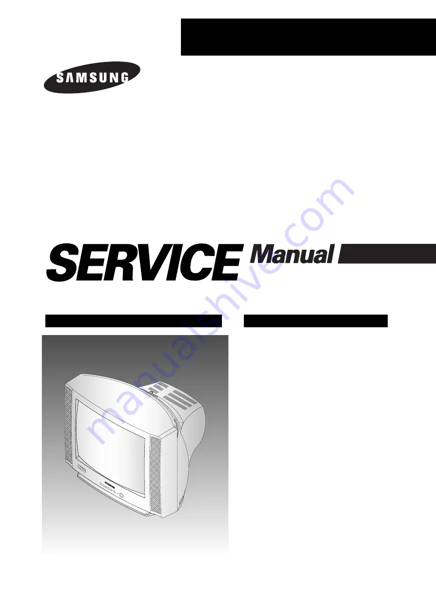
COLOR TELEVISION RECEIVER
Chassis :
K15D
Model :
CT1488BLFX/XAO
CT14F2FX/XAO
CT2088BLFX/XAO
CT20D8BWFX/XAO
COLOR TELEVISION RECEIVER
CONTENTS
Precautions
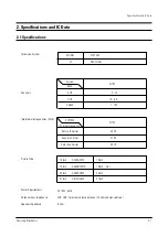
Specifications and IC Data
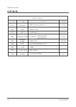
Disassembly and Reassembly
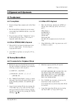
Alignment and Adjustment
Troubleshooting
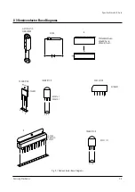
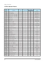
Exploded View and Parts List
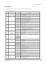
Electrical Parts List
Block Diagram
Wiring Diagram
Schematic Diagrams
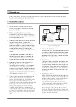
1.
2.
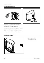
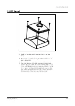
3.
4.
5.
6.
7.
8.
9.
10.
Summary of Contents for CT1488BLFX/XAO
Page 9: ...2 4 MEMO ...
Page 13: ...3 4 Samsung Electronics MEMO ...
Page 49: ...7 20 Samsung Electronics MEMO ...
Page 52: ...9 2 MEMO ...
Page 56: ...Schematic Diagrams 10 4 Samsung Electronics 10 4 MAIN 4 4 ...
Page 57: ...ELECTRONICS Samsung Electronics Co Ltd SEP 2002 Printed in Korea AA82 00147A ...


