
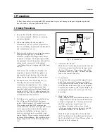


Precautions
Specifications and IC Data
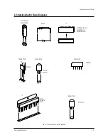
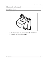
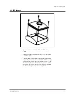
Disassembly and Reassembly
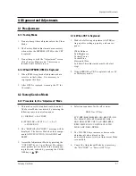
Alignment and Adjustments
Troubleshooting
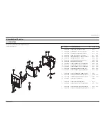
Exploded View and Parts List
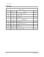
Electrical Part List
Block Diagram
Wiring Diagram
Schematic Diagrams
1.
2.
3.
4.
5.
6.
7.
8.
9.
10.
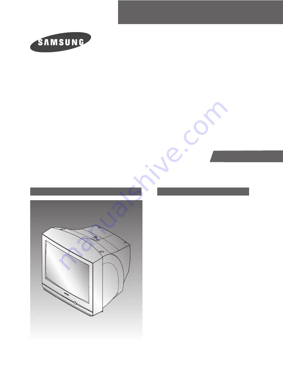
COLOR TELEVISION RECEIVER
Chassis :
K15D(N)
Model
:
CT20F3FNT/XAP
SERVICE
Manual
COLOR TELEVISION RECEIVER
CONTENTS
Summary of Contents for CT20F3FNT
Page 10: ...2 4 MEMO ...
Page 14: ...3 4 Samsung Electronics MEMO ...
Page 36: ...Schematic Diagrams 10 4 Samsung Electronics 10 4 MAIN 4 4 ...


