background image

Alignment and Adjustments

Samsung Electronics

4-7

Alignment and Adjustments

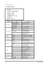
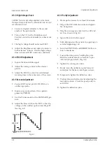
4-3-7  White Balance Adjustment

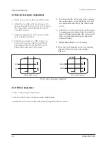
Fig. 4-2 Convergence Magnet Assembly

4 Pole Magnet

6 Pole Magnet

2 Pole Magnet

Clamper

Screw

2 POLE
PURITY

YOKE
CLAMP
SCREW

6 POLE
CONVERGENCE

4 POLE
CONVERGENCE

Fig. 4-3 Center Convergence Adjustment

31m/m

Vertical Green Belt

Fig. 4-4

1

2

(a) Set up

1. Warm up the TV for at least 30 minutes in the

White Pattern. 

2. Input a Toshiba pattern.

(b) High-Light Adjustment

Set SCT to 40

±

5 fL in the Factory Service 

Mode with using CA100. (See Fig. 4-4 

(c) Low-Light Adjustment

Set SBT to 1.5

±

0.2 fL in the Factory Service 

Mode with using CA100. (See Fig. 4-4 

)

Summary of Contents for CX6844N3X/XEE

Page 1: ...844W3X XET COLOR TELEVISION RECEIVER CONTENTS Precautions Specifications and IC Data Disassembly and Reassembly Alignment and Adjustment Troubleshooting Exploded View and Parts List Electric Parts List Block Diagram PCB Layout Diagram Wiring Diagram Schematic Diagrams 1 2 3 4 5 6 7 8 9 10 11 ...

Page 2: ... metal cabinets screwheads and control shafts The current measured should not exceed 0 5 milliamp Reverse the power plug prongs in the AC outlet and repeat the test Fig 1 1 AC Leakage Test 6 Antenna Cold Check With the unitÕs AC plug disconnected from the AC source connect an electrical jumper across the two AC prongs Connect one lead of the ohmmeter to an AC prong Connect the other lead to the co...

Page 3: ...ppear to have overheated or that are otherwise damaged should be replaced with parts that meet the original specifications Always determine the cause of damage or overheat ing and correct any potential hazards 15 Observe the original lead dress especially near the following areas Antenna wiring sharp edges and especially the AC and high voltage power supplies Always inspect for pinched out of plac...

Page 4: ...ssible conductive parts examples metal panels input terminals and earphone jacks 6 Insulation Checking Procedure Disconnect the power cord from the AC source and turn the power switch ON Connect an insulation resistance meter 500V to the blades of the AC plug The insulation resistance between each blade of the AC plug and accessible conductive parts see above should be greater than 1 megohm 7 Neve...

Page 5: ...ctrical charges that damage ESDs 5 Use only a grounded tip soldering iron when soldering or unsoldering ESDs 6 Use only an anti static solder removal device Many solder removal devices are not rated as Òanti staticÓ these can accumulate sufficient electrical charge to damage ESDs 7 Do not remove a replacement ESD from its protective package until you are ready to install it Most replacement ESDs a...

Page 6: ...F CII P AL I VHF UHF CX P AL B G SE C AM B G CK P AL B G D K SE C AM B G D K CB P AL B G CF SECAM L L PAL SECAM B G SYSTEM BAND PAL SECAM B G I PAL SECAM D K SECAM K1 PAL D VHF 2 12 1 13 2 9 UHF 21 69 21 69 13 57 SYSTEM BAND PAL SECAM B G PAL SECAM D K K1 PAL I SECAM L Picture IF Carrier 38 90 38 90 38 90 38 90 Sound IF Carrier 33 40 32 40 32 90 34 40 Color Sub Carrier 34 47 34 47 34 47 34 47 25 I...

Page 7: ...6S SOUND AMP 5W CH IC701 6 TDA9859 AUDIO PROCESSOR IC801 7 KA3S1265R SMPS IC 12A IC802 8 PC123Y PHOTO COUPLER IC803 9 78R05 SWITCHING REGULATOR IC804 10 KA7630 SWITCHING REGULATOR 5 8V IC901 11 SPM171EE MICOM IC902 12 24W16 EEPROM ICE01 13 4558 EW DRIVE AMP ICN01 14 TDA9814T SIF DETECTOR SECAM L NICAM MODULE ICN02 15 TDA9874H NICAM DEMODULATOR ICA01 16 LA7567N SIF DETECTOR A2 STEREO MODULE ICA02 1...

Page 8: ...884X Pin 56 SPM171EX Pin 52 24W16 Pin 8 TDA9859 Pin 32 IC TRANSISTOR TRANSISTOR KA7630 KA7812 IN G OUT TRANSISTOR TRANSISTOR 2SD1651 2SD1650 KSD5072 KSD5071 KSD1711 B C E E B C KSA815 Y KSA539 Y IC UPC574J or KA33V G1962 K2950M K9253M G3956M SAW FILTER 1 E C B KSR1012 KSR1010 KSR2010 Fig 2 1 Semiconductor Base Diagrams ...

Page 9: ...2 4 Samsung Electronics MEMO ...

Page 10: ...Disassembly and reassembly Samsung Electronics 3 1 3 Disassembly and Reassembly 3 1 Back Cover Removal 1 After removing the 7 screws pull the cabinet backwards ...

Page 11: ...e the AC cord from CN801 6 Separate the DC connector from CN401 7 Separate the CN501B 8P CRT connector from CN501 8 Separate the CNA05 5P A V side connector from CN602 9 Separate the CNA01 8P CRT connector from CN701 10 Separate the Focus Screen Wire from the FBT clamper 11 Separate the TBC wire 2P speaker wires from the wire clamper 12 Separate the CN701 CN602 connector from the wire clamper 13 S...

Page 12: ...r Removal Disassembly and reassembly Samsung Electronics 3 3 7 1 Remove the speaker by pressing the tension rib 1 Separate the speaker wires from D coil located on the bottom to the right side 2 Remove the screws ...

Page 13: ...CRT backwards 2 Caution Because of the high vacuum and large surface area of the picture tube be careful while handling it 1 Always lift the picture tube by grasping it firmly around the faceplate 2 Never lift the tube by its neck 3 Do not scratch the picture tube or apply excessive pressure Fractures of the glass may cause an implosion ...

Page 14: ...his adjustment must be the last step 4 2 Factory Service Mode 4 2 1 Procedure for the Adjustment Mode 1 This mode uses the standard remote control The Service Mode is activated by entering the following remote control sequence 1 STAND BY DISPLAY MENU MUTE POWER ON 2 The ÒSERVICE FACTORY Ó message will be displayed The Service Mode has three compo nents Adjustment Option and Reset 3 Access the Adju...

Page 15: ...ONTROLLED OSCILLATOR 0 1 VOL VOLUME INITIAL LEVEL 0 63 PSL PAL VERTICAL SLOPE 0 63 PVS PAL VERTICAL SHIFT 0 63 PVA PAL VERTICAL AMPLITUDE 0 63 PHS PAL HORIZONTAL SHIFT 0 63 PEW PAL E W WIDTH 0 63 PEP PAL E W PALABOLA 0 63 PEC PAL E W CORNER 0 63 PET PAL E W TRAPEZIUM 0 63 VSC VERTICAL SCROLL 0 63 TSC TELETEXT SUB CONTRAST 0 63 SA SEPARATION ADJUSTMENT STEREO 0 15 QEW Q 12 8 9 MODEL E W WIDTH 0 7 P...

Page 16: ...ode is not cancelled The AGING mode is cancelled by repressing the ÒHIDDENÓ or any key on the front pannel FACTORY MODE VALUE OSD INITIAL OSD INITIAL OSD INITIAL 2 CH LCO 1 FIXED TSC 20 FIXED AGC 10 VOL 25 SA 7 VCO 80 FIXED PSL 31 FIXED QEW 5 SBT 7 PVS 31 PCT 7 FIXED SCT 16 PVA 31 PTT 31 FIXED SCR 5 FIXED PHS 40 PHM 8 FIXED SC 11 FIXED PEW 38 PVP 31 FIXED RG 31 PEP 22 PHP 31 FIXED BG 31 PEC 22 NSR...

Page 17: ...ULT POLAND POLAND MODEL ONLY LANGUAGE WEST ENG GER FRA DUT SPA ITA SWE WEST EUROPE MARKET ENGLISH GERMANY FRANCE NETHERLANDS SPAIN ITALY SWEDEN EAST ENG CZE CRO RUM HUN POL EAST EUROPE MARKET ENGLISH CZECH CROATIA ROMANIA HUNGARY POLAND SYSTEM CF SECAM L L PAL SECAM B G CI PAL I UHF BAND ONLY CK PAL SECAM B G D K CX PAL SECAM B G CB PAL B G ATS OPTION ON OFF ATM FUNCTION NOT USED FIELD POL FIELD P...

Page 18: ...empt to connect or disconnect any wires while the TV is turned on Make sure that the power cord is disconnected before replacing any parts 8 To protect against shock hazard use an isola tion transformer 4 3 2 Automatic Degaussing A degaussing coil is mounted around the pic ture tube so that external degaussing after moving the TV should be unnecessary But the receiver must be properly degaussed up...

Page 19: ...K to an oscilloscope probe 2 Input a gray scale pattern Use a pattern generator PM5518 3 Use the Picture mode for the STANDARD pic ture 4 Adjust the Screen VR on the FBT so that the voltage on the oscilloscope becomes 140 2 5V See Fig 4 1 4 3 6 Purity Adjustment 1 Warm up the receiver for at least 20 minutes 2 Plug in the CRT deflection yoke and tighten the clamp screw 3 Plug the convergence yoke ...

Page 20: ...AMP SCREW 6 POLE CONVERGENCE 4 POLE CONVERGENCE Fig 4 3 Center Convergence Adjustment 31m m Vertical Green Belt Fig 4 4 1 2 a Set up 1 Warm up the TV for at least 30 minutes in the White Pattern 2 Input a Toshiba pattern b High Light Adjustment Set SCT to 40 5 fL in the Factory Service Mode with using CA100 See Fig 4 4 c Low Light Adjustment Set SBT to 1 5 0 2 fL in the Factory Service Mode with u...

Page 21: ...bs at the same time keeping the angle constant and superimpose the red and blue horizontal line in the center of the screen 6 Adjust the two tab pairs of the 6 pole magnets to superimpose the red and blue line onto the green Changing the angle affects the vertical lines and rotating both magnets affects the horizontal lines 7 Repeat adjustments 2 6 if necessary 8 Since the 4 pole magnets and 6 pol...

Page 22: ...ust PVS so that the picture is vertically centered 3 Adjust with PVA so that the top and bottom margins of the picture are 4 4 Adjust PHS so that the picture is horizontally centered 5 Adjust with PEW so that the left and right margins of the picture are 5 6 Input a crosshatch pattern 7 Adjust PEP PEC PET for vertical linearity 4 4 5 5 ...

Page 23: ...bleshooting 5 1 No Video Raster On No Sound Yes No Check Replace TU101 HC101 No Measure the Voltage of each of 8 pins of TU101 Check IC901 Pins 39 40 See No Video Sound OK See No Sound Video OK Check Replace IC901 IC201 IC902 IC701 Audio Module Yes ...

Page 24: ... Check IC804 Pin 9 5V Check Replace IC801 D802 Check Replace IC804 KA7630 DZ905 DZ804 Check IC901 Pin 18 Stand by 0V Normal 5V Check Replace IC901 Check IC901 Pin 8 4V Check Replace IC901 m com Check IC201 Pin 40 H out Check Replace IC201 Q402 Q403 No Check Q402 Q403 Check Replace DZ805 IC802 Yes Yes Yes ...

Page 25: ...IC201 Pin 6 CVBS Check Replace IC201 Check IC201 Pins 19 20 21 R G B OUT Check IC202 pin 27 Y IN Check Replace IC201 D205 DZ204 Check IC501 on the CRT PCB Check Replace IC501 Check Replace R505 HEATER 6 3Vrms CRT V999 Yes No Check IC201 Pin 12 37 8V Check Replace IC804 KA7630 Yes Yes 2Vp p ...

Page 26: ... Sound output CHECK REPLACE IC601 R601 R602 CHECK IC701 Pin 15 18 Yes Yes No Yes 1 14 15 2 5 5 Power OFF ON Repeatedly CHECK Q403 COLLECTOR H PULSE SEE NO POWER NO YES CHECK IC901 PIN26 H SYNC CHECK REPLACE IC901 Q907 C913 DZ402 NO YES CHECK IC301 PIN7 V BLANK CHECK REPLACE Q301 Q302 D304 YES NO CHECK PIN6 16 5V PIN1 14V CHECK REPLACE R409 R413 D407 D410 DZ302 DZ303 NO YES CHECK REPLACE IC301 IC20...

Page 27: ...lectronics 5 5 5 6 SMPS Power Supply Does Not Function 1 When F 802 is open C heck Replace F802 IC 801 D802 2 When F 802 is okay but SMP S does not function C heck Replace DZ801 DZ808 IC 802 DZ805 3 Others See 5 Troubleshooting ...

Page 28: ...61 40053A STOPPER PCB ALL MODEL HIPS HB WHT HB 1 1 9 3001 000150 SPEAKER 20W 8ohm 91dB 130Hz 2 1 10 6002 000514 SCREW TAPPING RH 2 M4 L15 ZPC BLK SWRCH18 8 1 11 AA61 10068A BRACKET PCB M2160 SPTE T0 3 1 1 12 AA95 40011V ASSY SOUND S51A NICAM 1 1 13 AA64 10347A KNOB CONTROL ABS HB BLK 6844 1 1 14 AA64 40249A INDICATOR LED ACRYL HB 6844 1 1 15 AA64 40243A WINDOW REMOCON PC 6844 1 2 AA03 10018Y CRT C...

Page 29: ...10W DA TP 2012 JA03 2007 000029 R CHIP 0OHM 5 1 10W DA TP 2012 JA04 2007 000029 R CHIP 0OHM 5 1 10W DA TP 2012 JA05 2007 000029 R CHIP 0OHM 5 1 10W DA TP 2012 JA06 2007 000029 R CHIP 0OHM 5 1 10W DA TP 2012 JA07 2007 000029 R CHIP 0OHM 5 1 10W DA TP 2012 JA08 2007 000029 R CHIP 0OHM 5 1 10W DA TP 2012 JA09 2007 000029 R CHIP 0OHM 5 1 10W DA TP 2012 JA10 2007 000029 R CHIP 0OHM 5 1 10W DA TP 2012 J...

Page 30: ...4 5 C419 2401 001397 C AL 470uF 20 25V GP 10x16mm 5mm T C421 2401 002619 C AL 47uF 20 25V GP TP 5x11 5 C422 2306 000122 C FILM MPPF 100nF 5 50V TP 7 3x4 0x5 0mm C423 2201 000556 C CERAMIC DISC 470pF 10 500V Y5P TP 7x4 5 C424 2401 001527 C AL 47uF 20 250V HR TP 13x25mm 5m C425 2305 000154 C FILM MPEF 100nF 5 400V TP 21 5x6 5x11 5 C427 2201 000984 C CERAMIC DISC 680pF 10 2KV Y5P TP 11x6 7 5m C504 22...

Page 31: ...5 45 5 73V 500mW D602 0401 000005 DIODE SWITCHING 1N4148 75V 300MA DO 35 TP D801 0402 000213 DIODE RECTIFIER ERB12 06 600V 1 0A DO 41 TP D802 0402 001160 DIODE BRIDGE D5SB60 600V 2 8A SIP 4 ST D803 0402 000546 DIODE RECTIFIER TVR10G 400V 1 0A DO 41 TP D804 0401 000005 DIODE SWITCHING 1N4148 75V 300MA DO 35 TP D805 0402 000231 DIODE RECTIFIER FMG G26S 600V 4A TO 220F ST D806 0402 000493 DIODE RECTI...

Page 32: ... R220 2001 000281 R CARBON 100OHM 5 1 8W AA TP 1 8X3 2MM R221 2001 000281 R CARBON 100OHM 5 1 8W AA TP 1 8X3 2MM R222 2701 000142 INDUCTOR AXIAL 1UH 10 2 5X3 4MM R223 2001 000617 R CARBON 3 9Mohm 5 1 8W AA TP 1 8x3 2m R224 2001 000429 R CARBON 1KOHM 5 1 8W AA TP 1 8X3 2MM R225 2001 001026 R CARBON 910ohm 5 1 8W AA TP 1 8x3 2mm R226 2001 000793 R CARBON 47OHM 5 1 8W AA TP 1 8X3 2MM R230 2001 000331...

Page 33: ...022 R CARBON S 33ohm 5 1 2W AA TP 2 4x6 4mm R901 2001 000290 R CARBON 10KOHM 5 1 8W AA TP 1 8X3 2MM R902 2001 000290 R CARBON 10KOHM 5 1 8W AA TP 1 8X3 2MM R903 2001 000066 R CARBON S 10Kohm 5 1 2W AA TP 2 4x6 4mm R904 2004 000218 R METAL 10KOHM 1 1 8W AA TP 1 8X3 2MM R905 2004 000218 R METAL 10KOHM 1 1 8W AA TP 1 8X3 2MM R906 2004 000218 R METAL 10KOHM 1 1 8W AA TP 1 8X3 2MM R908 2001 000241 R CA...

Page 34: ...ERAMIC CHIP 33nF 10 50V X7R TP 2012 CN22 2203 002442 C CERAMIC CHIP 330nF 80 20 25V Y5V TP CN23 2203 000389 C CERAMIC CHIP 15pF 5 50V NPO TP 2012 CN24 2203 000818 C CERAMIC CHIP 33pF 5 50V NPO TP 2012 CN25 2203 000925 C CERAMIC CHIP 470nF 80 20 50V Y5V TP CN26 2203 000192 C CERAMIC CHIP 100nF 80 20 50V Y5V TP CN27 2401 000603 C AL 1uF 20 50V GP TP 5x11 5 CN28 2203 000925 C CERAMIC CHIP 470nF 80 20...

Page 35: ...MM KLCE 2F REMOCON AA59 10117AREMOCON DP TM59 AA59 10116A ASSY CRT AA03 10018YCRT COLOR A66EAK071X01 380MG 28 110D AA39 20519ALEAD CONNECTOR ASSY YFH806 06 6 4 P 500MM 1617 ASSY SPEAKER 3001 000150 SPEAKER 20W 8ohm 91dB 130Hz AA39 20452F LEAD CONNECTOR ASSY YFH800 01 CLIP 1P 600MM 1617 Electric Parts List Samsung Electronics 7 7 Loc No Code No Description Specification Remark Loc No Code No Descri...

Page 36: ...16 AC INPUT AC230V OR 220 240V SMPS TRANS CRT SPM 171EE IC MCU TTX RGB AMP TDA6108 TUNER TELE4 108A FBT FUH 29A003 VERTICAL AMP LA7845 H OUT TR STR KA3S1265R KA7630 H E A T E R V H HV 16 5V 14V 16 5V 180V 5V 8V 15V 155V SIF SAW FILTER TDA9814T SIF DETECTOR TDA9874 NICAM DECODER TDA9859 TDA7297 SPEAKER 8W 10W X 2 AUDIO PROCESSOR 2CH AUDIO AMP AUDIO MODULE ...

Page 37: ...48 DZ302 107 121 DZ303 99 108 DZ304 102 131 DZ305 94 133 DZ306 118 135 DZ402 90 91 DZ403 75 165 DZ501 309 190 DZ502 316 190 DZ503 296 190 DZ505 321 190 DZ601 223 213 DZ602 223 215 DZ603 223 223 DZ604 223 220 DZ701 49 148 DZ702 54 148 DZ703 59 148 DZ704 41 141 DZ705 64 148 DZ801 231 33 DZ802 218 26 DZ803 150 122 DZ804 177 120 DZ805 183 12 DZ807 166 120 DZ808 209 19 DZ901 227 165 DZ904 211 145 DZ905...

Page 38: ...cs 10 1 FOCUS SW801 M I C O M S O U ND AMP CN602 P IP T T X MO D UL E T D A 8 8 4 4 T U N E R A U D I O M O D U L E CN701 CN502 CN401 S MP S T R ANS CN501 CN501B A S S Y P W B MA IN C R T ANODE DY SCREEN SOCKET CRT F B T CN701A CN06A CN05A R L ASSY PWB FRONT A V ...

Page 39: ...10 2 Samsung Electronics MEMO ...

Page 40: ...51 50 1 2 3 8 4 5 6 7 10 9 11 Schematic Diagrams 11 1 Samsung Electronics 11 Schematic Diagrams 11 1 MAIN Power 21 Power Line Signal Line 1 2 3 4 5 6 7 8 9 10 11 50 51 ...

Page 41: ...Schematic Diagrams 11 2 Samsung Electronics 11 2 MAIN Power 25 30 Power Line Signal Line 1 2 3 4 5 6 7 8 9 10 11 12 50 51 51 50 1 2 8 4 5 6 7 10 11 12 9 3 ...

Page 42: ...matic Diagrams 11 3 Samsung Electronics 11 3 PWB MAIN One Chip 13 29 30 28 27 26 25 24 23 22 18 19 20 17 21 15 16 32 31 14 Power Line Signal Line 24 23 25 26 27 28 29 30 31 32 22 21 20 19 18 17 16 15 14 13 ...

Page 43: ...Schematic Diagrams 11 4 Samsung Electronics 11 4 PWB MAIN u COM 33 41 42 40 34 39 38 37 35 36 Power Line Signal Line 33 34 35 36 37 38 40 41 42 39 ...

Page 44: ...Schematic Diagrams 11 5 Samsung Electronics 46 47 48 49 AUDIO MODULE 11 5 PWB MAIN SUB Power Line Signal Line 46 47 48 49 ...

Page 45: ...Schematic Diagrams 11 6 Samsung Electronics 11 6 PWB MAIN Sound Module Mono ...

Page 46: ...Schematic Diagrams 11 7 Samsung Electronics 11 7 PWB MAIN CRT Power Line Signal Line 43 44 45 43 43 45 45 44 44 OPTION ...

Page 47: ...Schematic Diagrams 11 8 Samsung Electronics 11 8 PWB MAIN SOUND MODULE STEREO ...

Page 48: ...Schematic Diagrams 11 9 Samsung Electronics 11 9 PWB MAIN SOUND MODULE NICAM ...

Page 49: ...Schematic Diagrams 11 10 Samsung Electronics 11 10 PWB MAIN A V FRONT VIDEO SWITCH RGB S W MODULE ...

Page 50: ...ELECTRONICS Samsung Electronics Co Ltd DEC 1998 Printed in Korea 3S51A 4411 ...

Reviews: