Alignment and Adjustments (TV)
4-2
Samsung Electronics
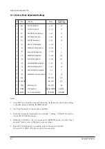
4-1-3 Factory Mode Adjustment Settings
Notes:
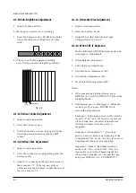
1. Press MUTE to enter Horizontal Line mode. In this mode, the screen voltage
is checked before adjusting the RGB cut-off.
2. Use Trap On mode to bypass the comb-filter.
3. In the Option mode, adjustments are usually “Analog” (“Digital” is used to
widen the AFT pull-in range).
4. When the VOLUME + key is pressed in the EEPROM mode, all of the “user-
adjusted” data is reset to the factory-preset values.
5. The ACS/V-CHIP mode is available only in USA and CANADA.
So set ACS/V-CHIP ON only for those two countries.
Initialization
MICOM Data
1
2
3
4
5
6
7
8
9
10
11
12
13
14
15
16
17
18
19
AGC
VCO
SCT
SCR
STT
RC
GC
BC
GG
BG
SB
VA
VS
HS
AFN
ACS/VCHIP
TRAP
OPTION
EEPROM
RF AGC Adjustment
PIF VCO Adjustment
SUB-CONTRAST Adjustment
SUB-COLOR Adjustment
SUB-TINT Adjustment
RED-CUT OFF Adjustment
GREEN-CUT OFF Adjustment
BLUE-CUT OFF Adjustment
GREEN-GAIN Adjustment
BLUE-GAIN Adjustment
SUB-BRIGHTNESS Adjustment
VERTICAL SIZE Adjustment
VERTICAL CENTER Adjustment
HORIZONTAL Phase Adjustment
3.58MHz Switch
AFT Adjustment
User Mode Initialization
No
Item
Function
Range
0 ~ 63
0 ~ 127
0 ~ 63
0 ~ 63
0 ~ 63
0 ~ 255
0 ~ 255
0 ~ 255
0 ~ 255
0 ~ 255
0 ~ 63
0 ~ 63
0 ~ 4
0 ~ 31
ON or OFF
ON or OFF
ON or OFF
ANALOG/DIGITAL
INITIALIZE
45
40
30
20
36
0
0
0
128
128
15
36
0
16
OFF
OFF
ON
ANALOG
INITIALIZE
Summary of Contents for CXJ1352AX
Page 2: ...ELECTRONICS Samsung Electronics Co Ltd JUL 2000 Printed in Korea 3V15A 1922 ...
Page 8: ...2 2 Samsung Electronics MEMO ...
Page 18: ...MEMO 3 10 Samsung Electronics ...
Page 28: ...MEMO 4 10 Samsung Electronics ...
Page 30: ...MEMO 5 2 Samsung Electronics ...
Page 48: ...MEMO 6 18 Samsung Electronics ...
Page 50: ...Exploded View Parts List 7 2 Samsung Electronics 7 2 Mechanical Parts Top Side Twin Deck ...
Page 51: ...Exploded View Parts List Samsung Electronics 7 3 7 3 Mechanical Parts Bottom Side Twin Deck ...
Page 85: ...8 34 Samsung Electronics MEMO ...
Page 89: ...Block Diagram 9 4 Samsung Electronics 9 4 Deflection Block Diagram ...
Page 90: ...Block Diagram 9 5 Samsung Electronics 9 5 Video Sound Signal Flow ...
Page 91: ...10 Wiring Diagram Wiring Diagram Samsung Electronics 10 1 ...
Page 94: ...PCB Layout Samsung Electronics 11 3 11 3 Main CONTROL ...
Page 97: ...Schematic Diagrams 11 3 Samsung Electronics 11 3 VCR POWER BLOCK ...
Page 100: ......


