Alignment and Adjustments (TV)
4-4
Samsung Electronics
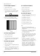
4-1-10 Sub-Brightness Adjustment
1. Input a Toshiba pattern.
2. Warm up the receiver for 10 minutes.
3. Enter the Factory mode. Set SB to the point
where the 6th point is brighter in the gray
scale.
4-1-13 Horizontal Size Adjustment
1. Input a lion head pattern.
2. Enter the Factory mode.
3. Adjust HS so that both left and right
of the pattern are 5.0±0.5.
4-1-14 When CRT Is Replaced
Do the following AFTER the basic purity and
convergence adjustments:
1. White Balance Adjustment
2. Sub-brightness Adjustment
3. Vertical Center Adjustment (VS)
4. Vertical Size Adjustment (VA)
5. Horizontal Size Adjustment (HS)
Notes :
1. After completing all adjustments, press
DISPLAY, 6, 1, 4 and POWER ON while in the
Stand By Mode.
2. Commercial use on/off displays: While the
receiver is off, re-press POWER ON to
restore the adjusted data.
Example 1: If the main power is off while the
receiver is “on” and the receiver is powered
off for a long time, the latest adjusted data
will remain intact when the power is
reapplied.
Example 2: If condition “1”—described
above—occurs while a tape is playing in the
“True Repeat On” mode, the set will revert to
True Repeat when power is reapplied.
Important: Check if the Commercial Use
mode is on. If so, switch it off. Also, it is
impossible to enter the Commercial Mode
when a tape is loaded (i.e., unload the tape
and press DISPLAY, 6, 1, 4, POWER ON).
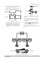
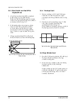
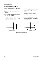
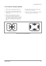
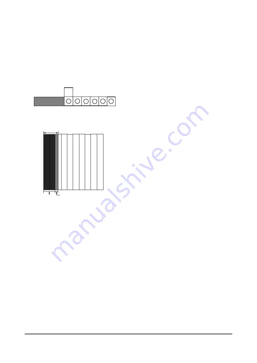
4. If there is no Toshiba pattern available,
use a 10 step pattern and adjust as follows:
4-1-11 Vertical Center Adjustment
1. Input a lion head pattern.
2. Enter the Factory mode.
3. Set VS so that the vertical center point in the
lion head pattern coincides with the CRT
center.
4-1-12 Vertical Size Adjustment
1. Input a lion head pattern.
2. After the vertical center adjustment, enter the
Factory mode.
3. Adjust VA so that both the top and bottom of
the screen are 3.5. If the top and bottom
values are not equal, adjust so that the sum of
the two values is 7.0.
W
5
4
3
2
1
6
2.5 BLOCKS
BLACK
HALF BLACK
Fig. 4-4
Summary of Contents for CXJ1352AX
Page 2: ...ELECTRONICS Samsung Electronics Co Ltd JUL 2000 Printed in Korea 3V15A 1922 ...
Page 8: ...2 2 Samsung Electronics MEMO ...
Page 18: ...MEMO 3 10 Samsung Electronics ...
Page 28: ...MEMO 4 10 Samsung Electronics ...
Page 30: ...MEMO 5 2 Samsung Electronics ...
Page 48: ...MEMO 6 18 Samsung Electronics ...
Page 50: ...Exploded View Parts List 7 2 Samsung Electronics 7 2 Mechanical Parts Top Side Twin Deck ...
Page 51: ...Exploded View Parts List Samsung Electronics 7 3 7 3 Mechanical Parts Bottom Side Twin Deck ...
Page 85: ...8 34 Samsung Electronics MEMO ...
Page 89: ...Block Diagram 9 4 Samsung Electronics 9 4 Deflection Block Diagram ...
Page 90: ...Block Diagram 9 5 Samsung Electronics 9 5 Video Sound Signal Flow ...
Page 91: ...10 Wiring Diagram Wiring Diagram Samsung Electronics 10 1 ...
Page 94: ...PCB Layout Samsung Electronics 11 3 11 3 Main CONTROL ...
Page 97: ...Schematic Diagrams 11 3 Samsung Electronics 11 3 VCR POWER BLOCK ...
Page 100: ......


