background image

WAECO

SERVICE

MICROWAVE OVEN

MICROWAVE OVEN

Manual

DE7712N

Timer

Operationg Voltage

Breaking Voltage

Input Current

Power Consumption

Operating frequency

Output Power

Main Fuse

Dimensions(WxHxD)

Outside(mm)

Oven(mm)

Net/Gross Weight

30 Minutes

24V DC

Min.21.5V, Max.29.5V

34A

820W

2,450MHz

500W (IEC-705)

32V DC, 80A

490 (W) X 282 (H) X 351 (D)

306 (W) X 190 (H) X 348 (D)

10.5 / 12.5 kg Approx.

Summary of Contents for DE7712N

Page 1: ...reaking Voltage Input Current Power Consumption Operating frequency Output Power Main Fuse Dimensions WxHxD Outside mm Oven mm Net Gross Weight 30 Minutes 24V DC Min 21 5V Max 29 5V 34A 820W 2 450MHz 500W IEC 705 32V DC 80A 490 W X 282 H X 351 D 306 W X 190 H X 348 D 10 5 12 5 kg Approx ...

Page 2: ... and latches 5 evidence of dropping or abuse c Before turning on microwave power for any service test or inspection within the microwave generating compartments check the magnetron wave guide or transmission line and cavity for proper alignment integrity and connections d Any defective or misadjusted components in the interlock monitor door seal and microwave generation and transmission systems sh...

Page 3: ...Primary and secondary interlock monitor switch 9 If the fuse is blown by the Interlock Monitor Switch Replace all of the following at the same time Primary door sensing switch and power relay as well as the Interlock Monitor Switch The correct adjustment of these switches is described elsewhere in this manual Make sure that the fuse has the correct rating for the particular model being repaired 10...

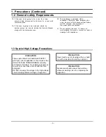
Page 4: ...with uninsulated tool during operation PRECAUTION Servicemen should remove their watches whenever working close to or replacing the magnetron 3 20 This appliance is equipped with a condenser Therefore when relocating the oven be sure to first disconnect the battery wait 20 seconds then disconnect the power cable connections 21 Do not operate the oven if it does not work properly Be sure to prevent...

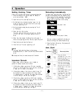
Page 5: ...eriod appears the voltage has returned to normal and you can use the oven again 3 If the battery voltage goes above 28 5V when operating the oven or 29 5V when the oven is idle the oven beeps 6 times and HI blinks on the display 4 If the battery voltage is high you can check to see if it has returned to normal by pressing the Cancel button If a blinking period appears the voltage has returned to n...

Page 6: ...fore operating the oven times can be increased using either the time pads or Start 30 s Button During operation time may only be added by using the Start 30 s Button Using the Cancel Button To stop cooking erase instructions and return the oven display to period press Cancel Button To correct a mistake you have just entered press Cancel once then r e enter the instructions Error Codes Error Items ...

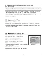
Page 7: ...move the air cover 4 Remove screws securing the magnetron to the wave guide 5 Take out the magnetron very carefully 6 Remove screws from the back panel 7 Take out the fan motor 8 Remove the oven lamp by pulling out from hole of air cover carefully NOTE1 When removing the magnetron make sure that its antenna does not hit any adjacent parts or it may be damaged NOTE2 When replacing the magnetron be ...

Page 8: ...s to prevent an excessive microwave leakage 1 Disconnect the oven from the power source 2 When fuse blows out by the operation of interlock monitor switch failure replace the primary interlock switch door sensing switch monitor switches and power relay 3 When the above three switches operate properly check if any other part such as Inverter P C B 80A blower motor or Sub P C B 5A is defective 1 Tak...

Page 9: ...cate only an open filament or a shorted magnetron To diagnose an open filament or shorted magnetron 2 Isolate the magnetron from the circuit by disconnecting its leads 3 A continuity check across the magnetron filament termi nals should indicate one ohm or less 4 A continuity check between each filament terminal and magnetron case should read open 1 Check continuity of the capacitor with the meter...

Page 10: ...rts in accordance with the wiring diagram and be sure to use the correct part number for the following switches Primary interlock and secondary interlock door sensing and the monitor switch replace all together Then follow the adjustment procedures below After repair and adjustment be sure to check the continuity of all interlock switches and the monitor switch 1 When mounting Primary switch and M...

Page 11: ...hen check continuity without the power source on To do otherwise may result in a false reading or damage to your meter 5 Do not touch any part of the circuit or the control circuit board since static discharge may damage it Always Touch ground while working on it to discharge any static charge built up Note Changing requires to follow minimum torque range 40 kg cm H V Trans Holder P C B MOSFET IRF...

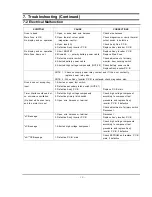
Page 12: ...ontact and if it has not continuity replace power relay also NOTE 2 When Ass y Inverter P C B is replaced check magnetron also Oven does not accept key input 1 Shorted or open tact switch 2 Defective secondary latch switch NOTE 1 3 Defective Ass y P C B Replace P C B main Timer Starts countdown but no microwave oscillation No heat while oven lamp and fan motor turn on 1 Defective high voltage comp...

Page 13: ...loded Views 19 D4 D3 D2 D9 D10 D1 D7 D8 D6 D5 M12 M25 M4 M3 M20 Sub P C B M5 M23 M24 M11 M6 M8 M26 M29 M1 M27 M22 M21 M17 M16 M2 I7 I4 I5 I8 I1 I2 M18 M19 M10 M9 B3 B2 B2 B4 B1 M7 M28 M15 M13 M31 M30 M14 C6 C3 C10 C9 C8 C7 C4 C5 C2 C1 I3 I6 ...

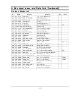
Page 14: ...2 V0 XAREC 1 M15 DE74 20102B TRAY COOKING GLASS T5 0 PI288 780G M745 1 M16 DE61 40066A FOOT PP BLK 3RD W 4 BASE PLEAT M17 DE80 00008A BASE PLATE SGCC1 Z T0 8 DA7311 ACDC 1 M18 DE31 10154A MOTOR SYNCHRONOUS M2HJ49ZR02 ST 16 50 60HZ 1 M19 DE71 60450B COVER MGT PP T2 W110 5 L109 28G 3RD 0 7 1 M20 DE39 00282A WIRE HARNESS DCN DE7711N DE7712N 12 24V 30KHz 1 M21 DE94 00345C ASSY CONTROL BOX TACT TYPE DE...

Page 15: ... 00069C BUTTON START ABS HR0370D WHT ORG SPRAY DE7711 12 1 C7 DE67 00071A BUTTON LED PERMITE ACRYL D GRY DA7711 ACDC 3 C PANEL C8 DE64 00135A WINDOW DISPLAY SAN CR5381G0126 SMOG DA7711 1 C9 DE72 00098D CONTROL PANEL ABS HR0370D DE7712N T2 5 PURE WHT 24V EUROPE 1 C10 RC DE7712N 00 ASSY PCB PARTS DE7712N 1 No Code No Description Specification Q ty Remark D1 DE64 00072C DOOR A DE7711 7712 XEG ABS HR0...

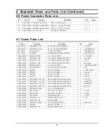
Page 16: ...EW A 2S 4X12 TOOTHED 2 body lat DE60 10082H SCREW A 2S 4X12 TOOTHED 2 con box DE60 10098A SCREW ASSY TAP TITE PH TC M4X8 SWRCH18A ZPC2 GLD W 1 CAV TCO DE60 10098A SCREW ASSY TAP TITE PH TC M4X8 SWRCH18A ZPC2 GLD W 2 GEAR MTR DE60 10098A SCREW ASSY TAP TITE PH TC M4X8 SWRCH18A ZPC2 GLD W 1 MEMB GRD DE60 10098A SCREW ASSY TAP TITE PH TC M4X8 SWRCH18A ZPC2 GLD W 2 MGT TCO DE60 10195A SCREW STAR POLE ...

Page 17: ...9 P C B Circuit Diagrams and Parts List 9 1 Main P C B Circuit Diagrams 23 a b c d ...

Page 18: ...OHM 1 1 10W DA TP 2012 1 R34 2007 000300 R CHIP 10KOHM 5 1 10W DA TP 2012 8 R11 12 14 29 31 40 41 2007 000346 R CHIP 120OHM 5 1 8W DA TP 3216 7 R17 23 2007 000468 R CHIP 1KOHM 5 1 10W DA TP 2012 4 R06 16 32 54 2007 000496 R CHIP 2 2KOHM 5 1 8W DA TP 3216 5 R24 28 2007 000575 R CHIP 220OHM 5 1 8W DA TP 3216 3 R35 36 37 2007 000671 R CHIP 2KOHM 5 1 10W DA TP 2012 9 R02 05 07 10 13 33 38 2007 000868 ...

Page 19: ...9 P C B Circuit Diagrams and Parts List Continued 9 3 Inverter P C B Circuit Diagram 25 f e ...

Page 20: ...9 P C B Circuit Diagrams and Parts List Continued 9 4 Drive P C B Circuit Diagram 26 g h ...

Page 21: ...RIDGE 250V 5A FAST ACTING 1 DE47 40024A HOLDER FUSE FH 51H 7 5A 1 No Code No Description Specification Q ty Remark I1 0402 001410 DIODE RECTIFIER ESJC32 08XP 7 5KV 0 35A 2 I2 0505 001552 FET SILICON IRFP064N 55V 110A 2 I3 2301 001483 C FILM MPEF 1 2NF 3KV 2 I4 2301 001484 C FILM MPEF 3 6NF 3KV 3 I5 3601 001220 FUSE 32VDC 80A FAST ACTING 1 I6 DE26 00065A TRANS H V SHV DE7712N 24VDC 1 I7 DE61 00195A...

Page 22: ...10 Wiring Diagrams and Operating Sequence 10 1 Wiring Diagram 28 A A NOTE 1 Door is opened 2 Ground ...

Page 23: ...inued 10 2 Description of Operating Sequence Test point in circuit diagram WAVE FORM Fan relay Lamp relay Power relay PWM output Out 1 Out 2 0 When oven is started initial operating status is shown below figure on off off on on off off on off on off on 6 6 ƒ 250Hz ...

Reviews: