background image

24

33.. F

Fiirrm

mw

wa

arree U

Up

pd

da

attee

1) Firmware version check method

a. Turn the power on, at the same time pressing LCD button of camera, MENU button and 

OK button.

b. Firmware version will display on TFT LCD.

Version : 1.14

2) Firmware upgrade method

a. Download the newest Firmware to SD card..  
b. If you insert SD card to camera and turn the power on, red LED will on. 
c. Firmware will update automatically and after 2∼3 minutes, camera will be OFF

automatically with beep sound. (In case of lots of change Data, it may take over 5 minutes.) 

d. Check the normal update of Firmware. 

44.. A

Ad

djjuussttm

meen

ntt m

meetth

hood

d ffoorr eea

acch

h iitteem

m.. 

1) Focus adjustment

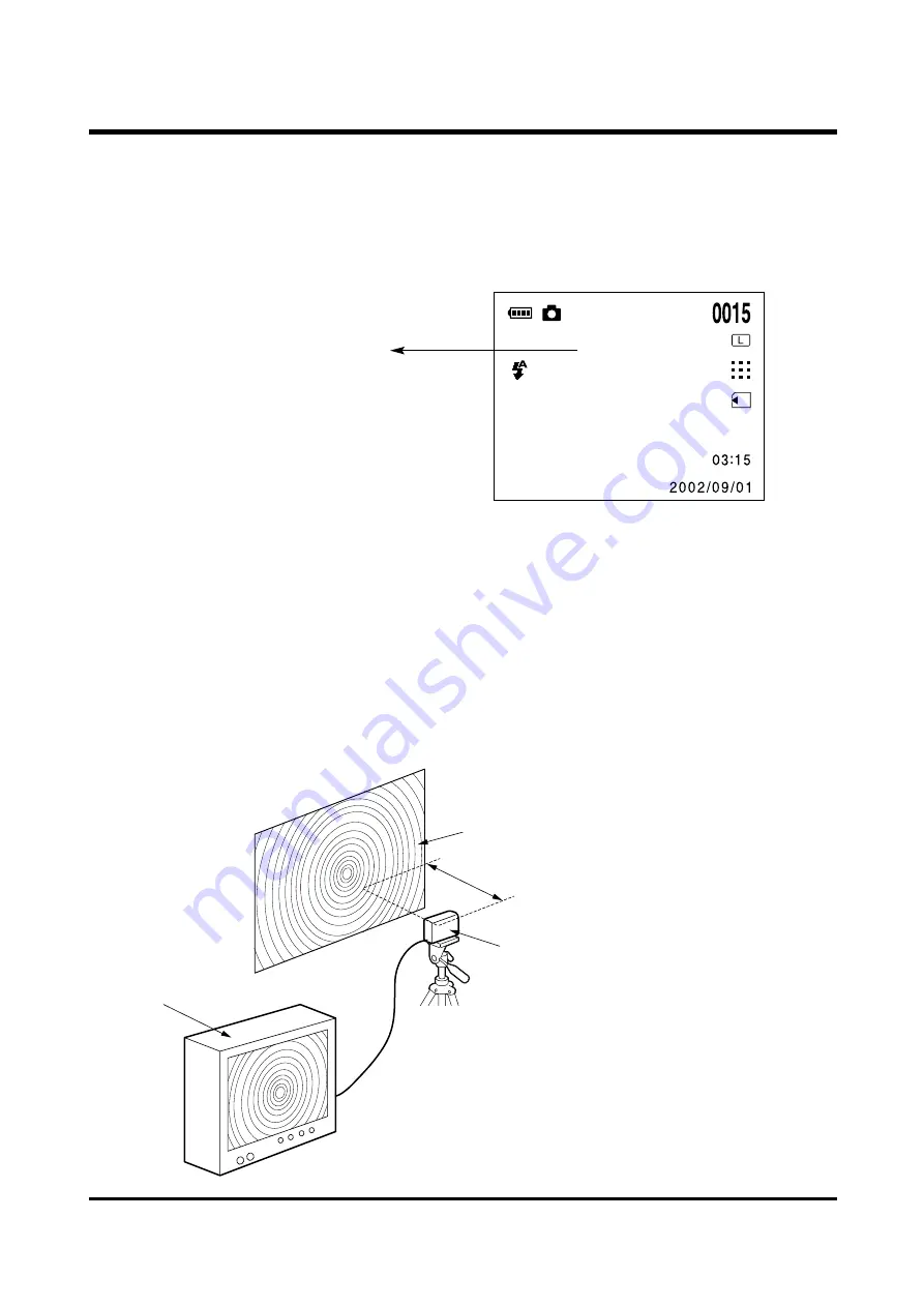
a. Set up a camera like below picture.(Download a Focus chart from ssa.net) 

b. Watching TV monitor, adjust 

a camera's image to be 
cleared by turning Lens. 

c. When the best condition of 

adjusted image, bond a Lens.   

Ⅳ..   A

A D

D JJ U

U S

S T

T M

M E

E N

N T

T

VE1.14

1.5m

Focus Chart

TV Monitor

Tripod

Camera

Summary of Contents for Digimax 101

Page 1: ...SERVICE MANUAL TECHWIN DIGIMAX 101 ...

Page 2: ...20 5 INITIAL PARTS LIST 22 Ⅳ Ⅳ A AD DJ JS SU UT TM ME EN NT T 1 REPLACEMENT PARTS AND ADJUSTMENT ITEMS 23 2 ADJUSTMENT TOOLS 23 3 FIRMWARE UPGRADE 24 4 ADJUSTMENT ITEMS 1 FOCUS ADJUSTMENT 24 2 BAD PIXEL ADJUSTMENT 25 3 AWB ADJUSTMENT 28 4 TRIG ADJUSTMENT 28 5 LCD ADJUSTMENT 29 6 STROBO ADJUSTMENT 30 Ⅴ Ⅴ P PR RO OD DU UC CT TS S C CO ON NS ST TR RU UC CT TI IO ON N 1 PARTS ARRANGEMENT FOR EACH PCB ...

Page 3: ...Sunset Tungsten Fluorescent Size 320x240 Recording time Memory capacity dependent Self timer 10 sec Media Internal memory 8MB flash memory External memory optional SD MMC card up to 256MB Guaranteed File Format Still image JPEG DCF DPOF Movie Clip AVI MJPEG Image Size Large 1280x1024 pixels Small 640x 512 pixe Capacity Large Super fine 15 Fine 22 Normal 44 8 16MB Small Super fine 30 Fine 60 Normal...

Page 4: ...patible monitor 24 bit color display recommended F FO OR R M MA AC CI IN NT TO OS SH H Power Mac G3 or later Mac OS 8 6 10 2 Minimum 32MB RAM 110MB of available hard disk space USB port CD ROM drive QuickTime 4 0 or later for Movie Clip Ⅰ Ⅰ S SP PE EC CI IF FI IC CA AT TI IO ON N 2 x AA alkaline 2 x Ni MH CR V3 batteries AC adapter Optional Dimensions WxHxD 108x56x37mm 4 3x2 2x1 5in Weight Approx ...

Page 5: ...mber of available shots remaining still image 0 0 1 5 Recording time while recording a movie clip 0 0 5 0 13 Message for canceling a movie clip recording 14 Digital zoom 15 Recording mode 6 PLAY mode 4 4 T TF FT T L LC CD D P Pa an ne el l M Ma ar rk k SHOT mode Ⅰ Ⅰ S SP PE EC CI IF FI IC CA AT TI IO ON N No Description Icons 1 Battery 2 Recording date 2002 09 01 3 Card indicator 4 Number of store...

Page 6: ... AC Adaptor USB Cable SD MMC Card Batteries Alkarain x2 IBM PC MACINTOSH 3 3V 2 0A Digimax 101 camera 5 5 C CO ON NN NE EC CT TI IO ON N D DI IA AG GR RA AM M Ⅰ Ⅰ S SP PE EC CI IF FI IC CA AT TI IO ON N ...

Page 7: ...r Ⅰ Ⅰ S SP PE EC CI IF FI IC CA AT TI IO ON N Power switch Lens Self timer lamp Viewfinder Flash DC input connection point Video connection terminal USB connection terminal Shutter button Battery chamber Card cover Card slot Battery chamber Strap eyelet ...

Page 8: ... CA AT TI IO ON N 5 function button LCD monitor Camera status LED p 15 Tripod socket MENU button MODE button LCD button Viewfinder FLASH LEFT button DELETE DOWN button SELF TIMER RIGHT button THUMBNAIL UP button OK button p 38 56 ...

Page 9: ...rage Driver menu on the Autorun frame 3 A start Installation window will open Click the Next button 4 Installation is complete Click the Finish button and the Digimax Viewer 1 0 installation will be started 5 The Digimax Viewer 1 0 installation window will be displayed as shown below Click Next button If you select Cancel at the step 2 the camera driver installation will be cancelled and a window ...

Page 10: ...ed 10 The Choose Setup Language window will open Select a language and click OK button 11 A Welcome window will be displayed Click Next to move to the next step If you select Cancel at the step 10 the MGI PhotoSuite III SE installation will be cancelled and a window for installing DirectX 8 1 will be displayed 6 The Software License Agreement window will display If you agree to it click Yes ...

Page 11: ...stallation is completed correctly the autoplay is registered automatically into the start menu program as shown below Click Next button 13 A Setup Type window will open Select setup type and click Next button 12 The Software License Agreement window will be displayed If you agree to this click Yes button 16 The Online Registration Utility window will be displayed Fill in the blanks and click the R...

Page 12: ...ectly Check Yes I want to restart my computer now button and click Finish button You must restart your computer after the installation or your computer can t recognize the camera as a Removable disk 17 Installation is complete Click the Finish button ...

Page 13: ...D D V VI IE EW WS S A AN ND D P PA AR RT TS S L LI IS ST T 1 17 1 7 1 21 1 13 1 2 1 18 1 19 1 6 1 3 1 1 1 4 1 5 1 24 1 22 1 23 1 16 1 15 1 14 1 20 1 9 1 12 1 10 1 11 1 8 1 1 F FR RO ON NT T C CO OV VE ER R A AS SS SE EM MB BL LY Y ...

Page 14: ...OVER 1 1 8 6003 0378 01A SCREW 1 1 9 6003 0377 01A SCREW 1 1 10 7409 1350 01A FLASH COVER TAPE A 1 1 11 7409 1352 01A FLASH COVER TAPE C 1 1 12 7409 1351 01A FLASH COVER TAPE B 2 1 13 9007 1854 01A TOP COVER ASS Y 1 1 14 7217 2722 01A RELEASE COVER 1 1 15 7217 2723 01A RELEASE BUTTON 1 1 16 6107 0522 01A RELEASE BUTTON SPRING 1 1 17 7217 2721 01A TOP COVER 1 1 18 7217 2724 01A POWER BUTTON 1 1 19 ...

Page 15: ...12 2 19 2 11 2 20 2 18 2 17 2 21 2 22 2 24 2 25 2 35 2 34 2 29 2 31 2 30 2 23 2 28 2 26 2 27 2 32 2 16 2 6 2 6 2 6 2 10 2 6 2 6 2 10 2 33 2 2 2 6 2 6 2 2 B BO OD DY Y Ⅲ Ⅲ E EX XP PL LO OD DE ED D V VI IE EW WS S A AN ND D P PA AR RT TS S L LI IS ST T ...

Page 16: ...A 1 2 16 7217 2715 01A BATTERY BOTTOM COVER 1 2 17 7011 0433 01A BATTERY CONTACT B 2 2 18 6107 0521 01A BATTERY SPRING 1 2 19 7411 0961 01A BATTERY PIN 1 2 20 9003 0196 01A VIEW FINDER ASS Y 1 2 21 7213 0332 01A VIEW FINDER COVER 1 2 22 7213 0333 01A VIEW FINDER MASK 1 2 23 6723 0018 01A VIEW FINDER LENS 2 1 2 24 6723 0020 01A VIEW FINDER LENS 1 1 2 25 7213 0334 01A VIEW FINDER HOLDER 1 2 26 2501 ...

Page 17: ...18 3 3 3 2 3 6 3 5 3 9 3 8 3 7 3 1 3 16 3 10 3 11 3 4 3 14 3 15 3 13 3 12 3 3 B BA AC CK K C CO OV VE ER R Ⅲ Ⅲ E EX XP PL LO OD DE ED D V VI IE EW WS S A AN ND D P PA AR RT TS S L LI IS ST T ...

Page 18: ...7217 2719 01A MODE KEY 5 WAY BUTTON 1 3 8 7217 2718 01A SELECT KEY 1 3 9 7411 0962 01A STRAP PIN 1 3 10 7409 1353 01A JACK PLATE A 1 3 11 7409 1354 01A JACK PLATE B 1 3 12 6003 0379 01A SCREW 1 3 13 6003 0378 01A SCREW 1 3 14 6003 0380 01A SCREW 3 3 15 6003 0382 01A SCREW 3 3 16 6003 0377 01A SCREW 1 Fig No Parts No Parts Name Q ty Remarks Ⅲ Ⅲ E EX XP PL LO OD DE ED D V VI IE EW WS S A AN ND D P P...

Page 19: ...20 4 4 P PA AC CK KI IN NG G I IT TE EM M 4 1 4 2 4 3 4 4 4 5 4 6 4 7 4 9 4 8 4 17 4 16 4 15 4 10 4 11 4 14 4 12 4 13 Ⅲ Ⅲ E EX XP PL LO OD DE ED D V VI IE EW WS S A AN ND D P PA AR RT TS S L LI IS ST T ...

Page 20: ...7 0095 02D CARD PRODUCT_MEXICO 1 4 8 6806 1368 01A USER MANUAL_KENOX_D 101 1 6806 1369 01A USER MANUAL_ENG 1 6806 1370 01A USER MANUAL_GER 1 6806 1371 01A USER MANUAL_FRA 1 6806 1372 01A USER MANUAL_SPA 1 6806 1373 01A USER MANUAL_ITA 1 6806 1374 01A USER MANUAL_CHI T 1 6806 1375 01A USER MANUAL_DUT 1 6806 1376 01A USER MANUAL_POR 1 6806 1377 01A USER MANUAL_SWE 1 6806 1378 01A USER MANUAL_DEN 1 6...

Page 21: ...86 01A SWITCH BOARD 35 14 3601 0005 01A FUSE 33 15 3722 0015 01A AC JACK 34 16 3409 0012 01A SWITCH MODE MENU 32 17 2601 0011 01A TRANSFOMER 33 18 2604 0019 01A TIGGER COIL 33 19 3722 0013 01A USB JACK 31 20 3722 0014 01A VIDEO JACK 31 21 3408 0010 01A Shutter SWITCH 35 22 7217 2722 01A RELEASE COVER 14 23 7217 2723 01A RELEASE BUTTON 14 24 6107 0522 01A RELEASE BUTTON SPRING 14 25 7217 2724 01A P...

Page 22: ...ester Adjust at LV 7 0 and check the flash on at LV 6 8 or flash off at LV 7 2 Others Osilloscope TV monitor Chart Focus chart Please contact to our website www ssa net and print the focus Chart on the paper from the 101CHART pdf Gray chart Standard 31 Gray Chart Main board Strobo board Switch board Lens module TFT LCD Update Firmware AWB adjustment Focus adjustment Bad pixel adjust Trig adjustmen...

Page 23: ...l update automatically and after 2 3 minutes camera will be OFF automatically with beep sound In case of lots of change Data it may take over 5 minutes d Check the normal update of Firmware 4 4 A Ad dj ju us st tm me en nt t m me et th ho od d f fo or r e ea ac ch h i it te em m 1 Focus adjustment a Set up a camera like below picture Download a Focus chart from ssa net b Watching TV monitor adjust...

Page 24: ...usting program How to install the adjusting program Ⅳ Ⅳ A AD DJ JU US ST TM ME EN NT T 1 Double click thesetup exe in the SDC1071 2 A Welcome window will open folder Click the Next button 3 Click Next 4 Click Next 5 The warning message will apperr when 6 Finish installing the driver please click the continue anyway button ...

Page 25: ... set a camera to Light source like below picture When setting Turn the power on at the same time pressing LCD button of camera MENU button and OK button e After connecting a camera if you click a Product button Product information window will appear like side If it doesn t appear after disassembling a camera connect it from first step and run it Ⅳ Ⅳ A AD DJ JU US ST TM ME EN NT T Double click Came...

Page 26: ...is time after covering a camera with hand or black thing click OK Confirm button j After finishing a Bad pixel test Find 0 Bad pixel will appear If the numger of Bad pixel is over 256 this camera had bad quality In this kind of case CMOS exchange is needed k When finishing a Bad pixel test after displaying Find 0 Bad pixel if you press Download bad pixel in low position of Camera Bad Pixel Write F...

Page 27: ...IG adjustment a Turn the power on at the same time pressing LCD button of camera MENU button and OK button TEST MODE b Put a AE Tester to LV 7 0 and set up a camera like below picture c In TEST mode change it to Movie mode by pressing Mode button d In Movie mode of TEST mode if you press Down button Trig adjustment will progress automatically e When finishing an adjustment it will radiate in LV 6 ...

Page 28: ...mended to use Adapter c Connect a oscilloscope like below picture d Connect a GND to GND of TFT LCD and make Check to be positioned left side of R26 Fig no 1 e At this time adjust the output signal by 3 9V 1 7V Fig no 2 Fig no 3 f When finishing an adjustment assemble a Cover Ⅳ Ⅳ A AD DJ JU US ST TM ME EN NT T ...

Page 29: ...ODE c Set up a camera like below picture It is whole dark condition around d In TEST mode change it to Movie mode by pressing Mode button e In Movie mode of TEST mode if you press Left button Strobo adjustment will progress automatically f When finishing an adjustment OK will appera on LCD 1 2m Reflector paper Tripod Camera Ⅳ Ⅳ A AD DJ JU US ST TM ME EN NT T ...

Page 30: ...31 1 1 P PA AR RT TS S A AR RR RA AN NG GE EM ME EN NT T F FO OR R E EA AC CH H P PC CB B A AS SS S Y Y 1 MAIN PCB Assembly a Parts Arrangement TOP Video Jack USB Jack Card socket Ⅴ PRODUCT CONSTRUCTION ...

Page 31: ...32 BOTTOM Ⅴ Ⅴ P PR RO OD DU UC CT T C CO ON NS ST TR RU UC CT TI IO ON N S W Menu Mode LED ...

Page 32: ...33 2 POWER PCB Assembly a Parts Arrangement TOP Ⅴ Ⅴ P PR RO OD DU UC CT T C CO ON NS ST TR RU UC CT TI IO ON N F1 FUSE Transformer Trigger coil ...

Page 33: ...34 Ⅴ Ⅴ P PR RO OD DU UC CT T C CO ON NS ST TR RU UC CT TI IO ON N BOTTOM AC JACK IGBT ...

Page 34: ...35 3 TOP PCB Assembly a Parts Arrangement Ⅴ Ⅴ P PR RO OD DU UC CT T C CO ON NS ST TR RU UC CT TI IO ON N Shutter Switch Power Switch ...

Page 35: ...S641632F NAND FLASH K9F6408U0B NOR FLASH SST39VF040 LCD CONT 1 6 COLOR LCD COM16T1151 SW1 BOARD SHUTTER POWER MCU BOARD SD CONNECTOR STROBE CIRCUIT STROBE CONDENSOR POWER CIRCUIT Main IC AT1382A AC JACK BATTERY CASI TV JACK BUZZER USB TO PC 3 3V TV POW BOARD SD CARD 2 2 B BL LO OC CK K D DI IA AG GR RA AM M ...

Page 36: ... TRAP BA0 BA1 SD_CMD SD_CLK SD_DATA 0 3 SM_RDY SM_CE SM_ALE FMGPIO 12 19 GPIO13 SD_PROT SD_DET 3 3V SD_WPROT MD 0 15 DA 0 5 SD_DATA 0 3 MA 0 11 RGB 0 9 FMGPIO 12 19 LCD_BL USBD LED_GREEN LEFT_SW FLASH_TRIG USB_D STBYB DOWN_SW SD_DET CKE LDQM GPCK BUZZER SD_PROT BA0 BA1 SM_CE SHUTTER_SW BATT_HIGH POL AC_IN CP GPIO13 TRAP VIDEO CAS EXCLK USB_ON RIGHT_SW UDQM SIOC LVCNTRL OK_SW GRES SENSOR_ON USBD SD...

Page 37: ...601 Q2 DTA114YE 02037 151 3 1 2 R21 1K 02137 115 C10 C 1 2 BUZ1 BUZZER PADX2_5 02437 H03 R15 18K 5 02137 1C2 1 2 R5 220K 02137 1D0 1 2 C3 0 1uZ 16V 02237 601 1 2 R2 20K 02137 183 1 2 L1 FBM 201209 102 02337 B26 1 2 CON3 USB CAM 42 02437 GK4 1 2 3 4 5 R19 33K 5 02137 126 1 2 R9 220K 02137 1D0 1 2 IC1 UMC2N UMT5 ROHM 02037 153 2 1 3 6 4 Q3 DTA144EE 02037 B76 2 1 3 R14 100K 1 1 16W 02137 128 1 2 Q4 D...

Page 38: ...37 2C0 R211 OPEN 1 2 C20 0 1uF 16V 02237 601 R210 0 1 2 R32 47K 02137 127 D2 1N4148WS 02037 C46 1 2 R34 12K 02137 1HC R27 20K 02137 030 1 3 2 C16 0 1uF 16V 02237 601 C15 2 2uF 25V 02237 282 R207 36 02137 1FS 1 2 R33 0 OPEN 1 3 2 C24 0 1uF 16V 02237 601 C13 1uF 25V 02237 2FR C19 10uF 25V 02237 2GM R205 1K 02137 115 1 2 C23 10uF 10V 02237 2GK C12 10uF 10V 02237 2GK Q14 2SC4617 02037 164 2 1 3 L9 22u...

Page 39: ...F 16V 02237 601 C0402 1 2 R66 22 02137 110 R0402 1 2 R57 1 5K 02137 117 R0402 1 2 R52 22 02137 110 R0402 1 2 R68 22 02137 110 R0402 1 2 R69 22 02137 110 R0402 1 2 R54 1M 02137 131 R0402 1 2 R49 OPEN 510K 02137 835 R0402 1 2 R50 0 02137 107 R0402 1 2 C93 0 1uF 16V 02237 601 C0402 C90 0 1uF 16V 02237 601 C0402 R70 22 02137 110 R0402 1 2 TP16 C79 20pJ 50V 02237 64J C0402 1 2 TP21 R56 33 02137 149 R04...

Page 40: ...C35 0 1uZ 16V 02237 601 C0402 1 2 C123 0 1uZ 16V OPEN C0402 1 2 R76 10K 02137 106 2 1 C41 22uF 10V C1206 02237 2GB 1 2 U2 OV9620 02037 E89 LCC48_1 0_70 6 7 18 19 30 31 42 8 9 10 11 12 13 14 15 16 17 20 21 22 23 24 25 26 27 28 29 32 33 34 35 36 37 38 39 40 41 43 44 45 46 47 48 1 2 3 4 5 VrLOW PWDN ASUB VrAD2 XCLK2 PCLK MENB FREX SRAMT RESET SCCB AD4CH VGA FSIN VcCHG AVDD AGND ADVDD ADGND DVDD DGND ...

Page 41: ...1 C0402 R86 10K 02137 106 R0402 1 2 R88 10K 02137 106 02137 106 R0402 1 2 C111 0 1uZ 16V 02237 601 C0402 C110 0 1uZ 16V 02237 601 C0402 U5 K9F6408U0B TCB0 02037 G30 TSOP44 2 3 8 9 7 13 32 44 1 16 6 41 42 4 17 38 37 23 39 36 15 28 14 5 18 20 29 31 40 25 27 19 21 30 22 35 24 26 10 43 CLE ALE N C N C N C N C N C VCC VSS N C N C R Bb REb WEb N C N C N C VCC N C N C N C N C N C WPb I O0 I O2 N C N C GN...

Page 42: ...6 UMG9N TR_UMT5 02037 B13 2 1 3 5 4 TP26 C122 0 1uF C0402 02237 601 1 2 S1 MODE BUTTON 02437 D34 LED1 02037 413 1 2 Q11 DTC143EUA 02037 B06 2 1 3 PW 1 R94 100K 02137 128 1 2 R99 1K 02137 115 R0402 1 2 D4 DAN222 TR_EMT3 02037 240 1 2 3 R96 100K 02137 128 1 2 R104 0 R0402 02137 107 R100 47K R0402 02137 127 MODE_SW 5 MENU_SW 5 POWER_ON 5 POWER_OFF 5 POWCTRL 5 SPM 1 LED_SELF 5 POWER_SW 1 5 Ⅴ Ⅴ P PR RO...

Page 43: ...METHOD OF MAIN DISPRODUCT METHOD OF MAIN DISPRODUCT REPAIR IN EACH BOARD REPAIR IN EACH BOARD MODEL DIGIMAX 101 ...

Page 44: ...1 1 MAIN BOARD TOP MAIN BOARD TOP BAD SD CARD RECOGNITION BAD SOLDRING BAD WORKING U5 HAULT ON SAVING IMAGES INTERNAL MEMORY INCLUDING EEPROM CARD LOCK LIGHT ERROR BAD SOLDRING C MOS U2 BAD WORKING Y2 ...

Page 45: ...BAD WORKING Y1 ELETRIC CURRENT UNDER 10uA BAD WORKING IC4 ELECTRIC CURRENT IS 200ma WITH IT S POWER ON ADJUST F W UP AWB TRIG STROB WHEN CHANGING BATTERY CAPACITY FOR DISPLAY TFT LCD REAR SCREEN VR FOR TFT LCD ADJUSTMEN T ...

Page 46: ...E TUBE BAD S T FLASH T2 BAD S T CHARGE T1 BAD WORKING F1 3A BAD WORKING U2 SWITCH POWER IC TEMPORAL ELECTRIC CURRENT GENERATES UNDER 100MA WITH POWER ON BAD WORKING J1 DC JACK ONE IS WORKING ANOTHER ONE IS NOT BETWEEN BATTERY AND ADAPTER ...

Page 47: ...3 TOP BOARD BAD WORKING SW1 BAD S H WORKING SB ...

Page 48: ... WORK 3 82607067 82602040 83105943 02 12 02 12 03 01 POWER ON NG FUSE F1 SHORT 4 83108049 03 01 POWER ON NG POWER BOARD PART EROSION 5 82602040 02 12 POWER ON LED LIGHT HALT SOLDERING DISPRODUCT OF POWER PCB Q2 SUB SYSTEM 6 82602111 02 12 POWER ON LED LIGHT HALT BAD SOLDERING OF POWER PCB U2 AT1382 7 83108149 03 01 POWER ON안됨 BAD SOLDERING OF POWER PCB L2 8 82606019 02 12 POWER ON LED LIGHT HALT O...

Page 49: ... 2 DISPRODUCT 1 DISPRODUCT 8 DISPRODUCT 9 비고 DISPRODUCT 19 25 DISPRODUCT 26 DISPRODUCT 29 비고 ...

Reviews: