6-1
6. PCB Diagram
6. PCB Diagram
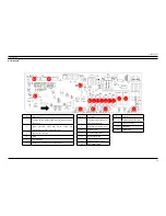
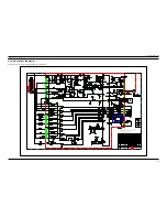
6-1. Main PCB
Location
Description
1
5V, GND, TX ,RX ,Wake up_TXD, Wake up_RXD, 12V, Relay
source 12V
2
GND,
Thermistor,
Float
S/W,
Water
softener
S/W,
Sychronous motor S/W,
Flow meter out, 5V
3
Micom Writer connector
4
GND
5
AC1, AC2, HPS
6
Dispensor,
Circulation Pump , Water softener
Location
Description
7
Sychronous motor, Fan motor,
Electrical Safety Hose
8
Drain Pump, Power(AC1, AC2)
9
Dispensor relay
10
Circulation Pump relay
11
Water softener relay
12
Sychronous motor
relay
13
Fan motor relay
Location
Description
14
Electrical Safety Hose relay
15
Drain Pump relay
16
Main relay
17
Heater relay
Y
X
\
]
^
Z
_
[
X]
X^
`
XW
XX
XY
XZ
X[
X\


