background image

5-11

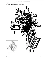
5. Exploded Views and Parts List

L

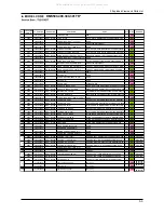
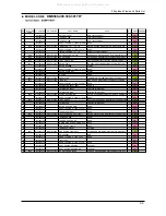
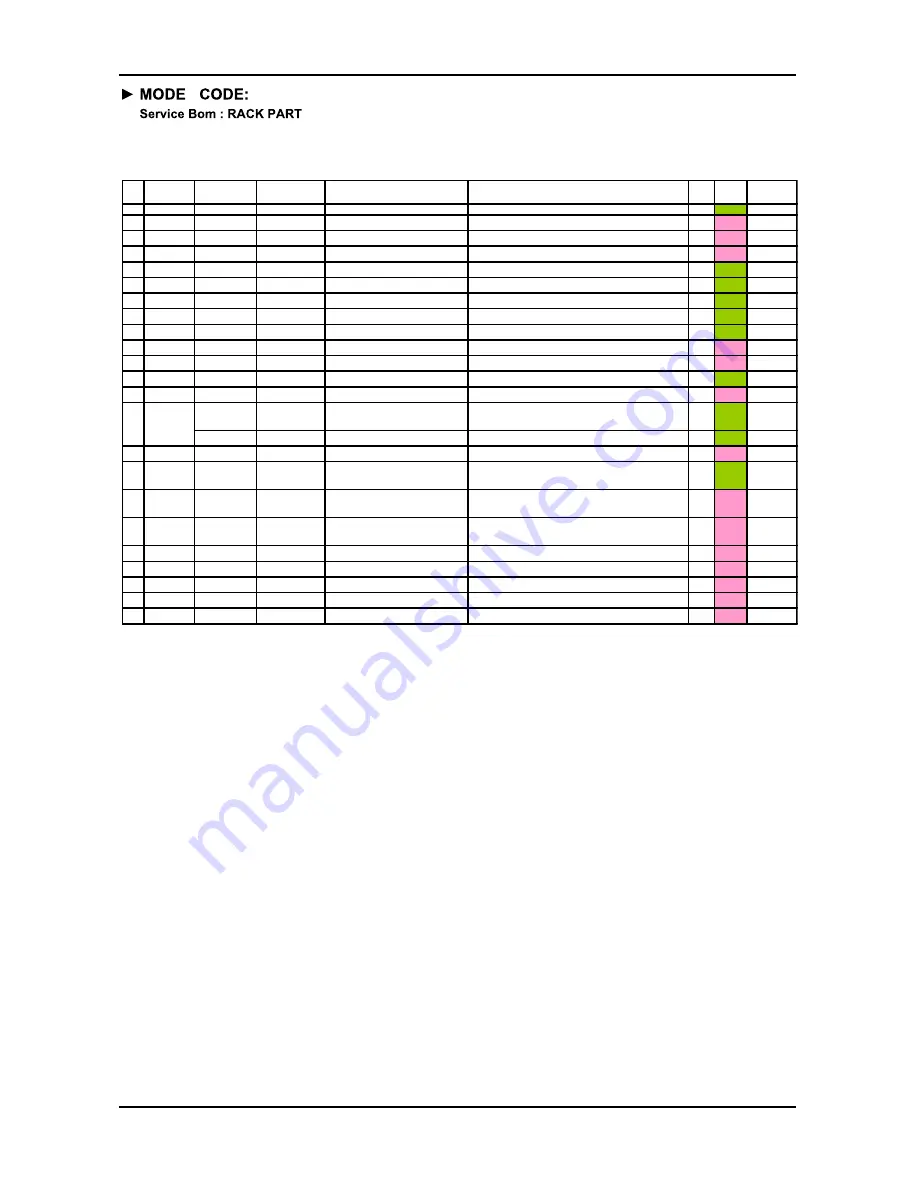
DMS500,400,300,301TR*

NO.

LOCATION

CODE

TY- PART NO.

SS-PART NO

PART NAME

SPEC

Q'TY Status

REMARK

1

F215

5122435000

DD82-01020A

LOWER RACK ASS'Y(SS)

A/S ASSY-LOWER RACK;DMS400TRW/XFA,DMS400

1

'SA'

2

5122507000

LOWER RACK INSERT-1

MSWR6

2

'SNA'

3

5122508000

LOWER RACK INSERT-2

MSWR6

2

'SNA'

4

5122509000

LOWER RACK INSERT-3

MSWR6

1

'SNA'

5

F232

5122439000

DD81-01244A

WIRE TINE

A/S-WIRE TINE;DMS400TRW/XFA,WIRE TINE,DM

4

'SA'

6

F284

5122449000

DD81-01245A

INSERT STOPPER

STOPPER-INSERT;DMS400TRW/XFA,DMS400TUB/X

2

'SA'

7

F255

5122450000

DD81-01246A

INSERT HOLDER

HOLDER-INSERT;DMS400TRW/XFA,DMS400TUB/XE

11

'SA'

8

F278

5120878300

DD81-01247A

RACK ROLLER HUB-GRAY

ROLLER-HUB;DMS400TRW/XFA,DMS400TUB/XEO,F

8

'SA'

9

F279

5120888800

DD81-01248A

LOWER RACK ROLLER-GRAY

ROLLER-LOWER RACK;DMS400TRW/XFA,DMS400TU

8

'SA'

10

5122447000

RACK HANDLE UPPER

PP+TALC30%

1

'SNA'

11

5122448000

RACK HANDLE LOWER

PP+TALC30%

1

'SNA'

12

F205

5122453000

DD82-01021A

CUTRELY BASEKT ASS'Y

A/S ASSY-CUTRELY BASEKT;DMS400TRW/XFA,DM

'SA'

13

5122439000

WIRE TINE

POM

1

'SNA'

5122434000

DD82-01019A

UPPER RACK ASSY' (SS)

A/S ASSY-UPPER RACK;DMS400TRW/XFA,DMS400

1

'SA'

DMS500TR*
DMS400TR*
DMS301TR*

5122434100

-

UPPER RACK ASSY' (SS-HEBA2)

'SA'

DMS300TR*

15

5122515000

UPPER RACK INSERT PIN

MSWR6

1

'SNA'

16

F274

5122437000

DD81-01242A

UPPER RACK INSERT

RACK-UPPER INSERT;DMS400TRW/XFA,DMS400TU

1

'SA'

DMS500TR*
DMS400TR*
DMS301TR*

17

5122440000

ADJUSTER ASS'Y(L)

ASS'Y

1

'SNA'

DMS500TR*
DMS400TR*
DMS301TR*

18

5122441000

ADJUSTER ASS'Y(R)

ASS'Y

1

'SNA'

DMS500TR*
DMS400TR*
DMS301TR*

19

5122451000

CUP SUPPORT(SS)

PP+TALC30%

4

'SNA'

20

5121842100

UPPER ROTOR PIPE-ass'Y

PP+TALC30%

1

'SNA'

21

5121810101

UPPER ROTOR ASSY

PP+TALC30%

1

'SNA'

22

5120879400

UPPER RACK ROLLER

PP+TALC30%

1

'SNA'

DMS300TR*

23

5120878300

RACK ROLLER HUB-GRAY

PP+TALC30%

1

'SNA'

DMS300TR*

14

F225

All manuals and user guides at all-guides.com

Summary of Contents for DMS300TR series

Page 1: ...information Safety Instructions Disassembly and Reassembly Troubleshooting Exploded Views and Parts List PCB Diagram Wiring Diagram Schematic Diagram Reference 1 2 3 4 5 6 7 8 9 DMS500TR DMS400TR DMS300TR DMS301TR DMS300 301 400 500 Series All manuals and user guides at all guides com a l l g u i d e s c o m ...

Page 2: ...ror check list 4 3 5 Exploded Views and Parts List 5 1 5 1 DOOR ASS Y DMS TR 5 2 5 2 TUB ASS Y DMS TR 5 4 5 3 BASE ASS Y DMS TR 5 6 5 4 SUMP ASS Y DMS TR 5 8 5 5 RACK ASS Y DMS TR 5 10 6 PCB Diagram 6 1 6 1 Main PCB 6 1 6 2 Terminals MAIN PBA 6 3 Terminals DISPLAY LED 4 3 Trouble Shooting Guide 4 6 7 Wiring Diagram 7 1 7 1 Old Wiring Diagram DMS TR 7 1 8 Schematic Diagram 8 1 8 1 MAIN CONTROL DMS ...

Page 3: ... breaker or power cable before servicing Failing to do so may result in a risk of electric shock ࣃ Do not allow consumers to connect several appliances to a single power outlet at the same time 7KHUH LV D ULVN RI UH GXH WR RYHUKHDWLQJ ࣃ When removing the power cord make sure to hold the power plug when pulling the plug from the outlet DLOLQJ WR GR VR PD GDPDJH WKH SOXJ DQG UHVXOW LQ UH RU HOHFWULF...

Page 4: ...r it touches the tub and causes noise and electric leakage ࣃ After Servicing Check for any water leakage Perform a test run for the dishwasher using the standard normal cycle and check ZKHWKHU WKHUH LV DQ ZDWHU OHDNDJH WKURXJK WKH ÀRRU VHFWLRQ RU WKH SLSHV ࣃ Do not allow consumers to repair or service any part of the dishwasher themselves This may result in personal injury and shorten the product ...

Page 5: ... a sharp tool or object This may result in electric shock or damage to the product ࣃ During Servicing When wiring a harness make sure to seal it completely so no liquid can enter 0DNH VXUH WKDW WKH GR QRW EUHDN ZKHQ IRUFH LV H HUWHG ࣃ Check if there is any residue that shows that liquid entered the electric parts or harnesses If any liquid has entered into a part replace it or completely remove an...

Page 6: ...easure the insulation resistance between the power wires and the grounding wire of the GLVKZDVKHU 7KH YDOXH PXVW EH JUHDWHU WKDQ 0 ZKHQ PHDVXUHG ZLWK D 9 Megger ࣃ KHFN ZKHWKHU WKH SURGXFW LV OHYHO ZLWK WKH ÀRRU KHFN LI WKHUH DUH DQ GHIRUPDWLRQV LQ WKH VLQN KHFN WKDW WKH GLVKZDVKHU LV UPO LQVWDOOHG WR WKH VLQN 9LEUDWLRQV FDQ VKRUWHQ WKH OLIHWLPH RI WKH SURGXFW ࣃ All manuals and user guides at all g...

Page 7: ...ung uses 3 wash arms tRp upper and lRwer EYery arms jets upper and lRwer side Especially water spraying arm in the tRp is rRtRr type like upper and lRwer s 2 4 fRlds filter system FRur fRlds filter system and fRRd dipRser breaks dRwn fRRd particlesand remnants frm the plates glasses pRts and pans ans cutlery in the dishwasher FRRd particles are brRken dRwn by a stainless steel blade and pass and i...

Page 8: ...All manuals and user guides at all guides com ...

Page 9: ...p aqua stop aqua stop standard hose standard hose standard hose standard hose water fill Sensor yes yes yes yes yes yes yes yes Overflow Sensor yes yes yes yes yes yes yes yes Low Level water Sensor yes yes yes yes yes yes yes yes Automatic Temperature Sensor yes yes yes yes yes yes yes yes Detergent Dispenser yes yes yes yes yes yes yes yes Last Cycle Memory yes yes yes yes yes yes yes yes Wash L...

Page 10: ...h 50mm yes One Touch 50mm 70 Inlet Water Capability yes yes yes yes yes yes yes yes Child Lock yes yes yes yes yes yes yes yes Drain Hose yes yes yes yes yes yes yes yes Hard Countertop Installation yes yes yes yes yes yes yes yes Leveling Screws yes 0 to 70mm yes 0 to 70mm yes 0 to 70mm yes 0 to 70mm yes 0 to 70mm yes 0 to 70mm yes 0 to 70mm yes 0 to 70mm Rinse Aid Dispenser yes yes yes yes yes y...

Page 11: ...GULYHU 3KLOLSV ÀDW 7RU 7 Preparation for parts replacement 1 Take out the residual water inside the product Drain the water by operating the drain pump ORVH WKH ZDWHU VXSSO YDOYH 3 Turn off the power disconnect power cable You must turn off the circuit breaker connected to the product 3XOO RXW WKH XQLW IURP WKH VLQN DQG OD LW RQ WKH ÀRRU Be careful of the drain hose when pulling out the unit All m...

Page 12: ...HYHQW WKH KDQGOH DQG IUDPH IURQW from being scratched After removing them make sure to hold the tub front with your hand while you are working as the tub may close and harm you 3 Pull down a outer door ass y Separate Outdoor Ass y 2 Contol panel ass y 2 Remove the four 4 screws holding the control panel ass y in place 1 Remove the connectors of main lead wire and the dispensor 3 Separate control p...

Page 13: ...Y Separate outdoor ass y Separate control pannel ass y 4 Display P C B ass y Separate outdoor ass y Separate control pannel ass y Separate Latch ass y 1 Remove the five 5 screws holding Display P C B ass y separate Display P C B from control panel ass y 2 Push the hooks fixing Display P C B ass y and Caution When reassemble the Display P C B ensure to place the PAD BUTTON on original location All ...

Page 14: ... counterclockwise 5 Remove the FAN DUCT CAP Draw the fan duct lower 2 Remove the two 2 screws holding the DOOR BRACKET and the ground wire 4 Hold and remove the FAN ASS Y which are located at the front of the INNER DOOR Use a jig If you have no jig use a tool such as a pair of long nose pliers Remove it carefully so that the part is not damaged FAN ASS Y All manuals and user guides at all guides c...

Page 15: ...dispenser Caution The connectors are of the locking type and are hard to remove Be careful not to break them when removing them 2 Remove the six 6 screws holding the INNER DOOR and the two 2 bracket dispensers in place Caution 7KH GLVSHQVHU LV HG WR WKH WXE IURQW ZLWK D KRRN 8VH D ÀDW VFUHZGULYHU WR UHPRYH LW IURP WKH WXE IURQW Caution Be careful as the inner door is sharp All manuals and user gui...

Page 16: ...he PLINTH FACIA in place 2 Remove the two 2 screws holding the FRONT FRAME SUB ASS Y 3 Remove the two 2 screws holding the MAIN PCB HOUSING ASS Y and pull dawn it Be careful to avoid breaking them because they are connected with a hook You can remove FRONT FRAME SUB ASS Y 4 Remove all connectors connected the PCB ASS Y All manuals and user guides at all guides com a l l g u i d e s c o m ...

Page 17: ... assembling Check hook of bottom 2 Remove the TOP TABLE ASS Y Slide the TOP TABLE ASS Y backward and lift up it 3 Remove the ten 10 screws holding the BACKCOVER and HOUSING L R You can remove BACK COVER Lift up backcover 4 Remove the two 2 screws holding the TOP BRACKET and remove four 4 screws holding the HOUSING L All manuals and user guides at all guides com ...

Page 18: ...DOOR ASS Y Caution Take care when holding and removing the HINGE FRAME with a tool as it may bounce and harm you UPPER ROTOR PIPE ASS Y 10 Upper rotor pipe ass y 1 Remove the RACK ROLLER STOPER and separate UPPER RACK ASS Y from TUB ASS Y 2 Pull UPPER ROTOR PIPE ASS Y for backward Be careful to avoid breaking them because they are connected with a hook 3 Separate the UPPER ROTOR PIPE ASS Y into th...

Page 19: ...2 Remove TOP ROTOR ASS Y Be careful to avoid breaking them because they are connected with a hook 12 Lower rotor assy 1 Lift up LOWER ROTOR ASS Y like figure 13 Filter ass y 1 Remove the COARES FILTER by rotating it counter clock wise 2 Remove the FINE FILTER and MICRO FILTER OUTER LOWER ROTOR ASS Y All manuals and user guides at all guides com ...

Page 20: ...arate top table ass y Ƒ Separate housing L R Ƒ Separate out door Ƒ Separate control panel ass y Ƒ Separate Inner door sub ass y Ƒ Separate filter ass y Manifold elbow ass y 2 Remove the ten screws for holding TUB ASS Y and ground wires 1 Use your hand to hold the AIR BREAK and rotate the AIR BREAK CAP Use a jig to remove by rotating the AIR BREAK CAP If you have no jig you can use a pair of long n...

Page 21: ...arate filter ass y Manifold elbow ass y 3 You can remove the TUB ASS Y like figure 1 Remove WATER SOFTNER CAP by rotating it counterclockwise Use a jig to remove by rotating the WATER SOFTNER RING If you have no jig you can use a pair of long nose pliers 2 Remove WATER SOFTNER RING by rotating it counterclockwise Caution Be careful as the tub is sharp All manuals and user guides at all guides com ...

Page 22: ...te air break ass y 1 Remove DRAIN HOSE HOLDER using a screw driver 2 Remove DRAIN HOSE for back of product Separate top table ass y Be careful to avoid breaking them because they are connected with a hook 3 Remove the two 2 DRAIN HOSE connectors using a screw driver 4 Remove the two 2 screws holding the INLET VALVE COVER 5 You can remove the ELECTRICAL for back of product STANDARD HOSE STANDARD HO...

Page 23: ...move the POWER CORD ASS Y for back of BASE PANEL ASS Y Ƒ Separate top table ass y 2 Remove the two 2 screws holding POWER CORD ASS Y in place 5 Remove the two 2 screws holding NOISE FILTER ASS Y in place 6 You can remove the NOISE FILTER ASS Y Caution When reassemble the NOISE FILTER ASS Y ensure to place the connectors on original location like figure terminal number housing color terminal number...

Page 24: ...Separate top table ass y 20 Water Softener ass y Ƒ Separate air break ass y 1 Remove the all connectors on both sides of the WATER SOFTENER ASS Y 3 You can remove the WATER SOFTENER ASS Y 21 Float switch ass y Ƒ Separate housing L R Ƒ Separate tub ass y Ƒ Separate top table ass y 1 Remove the MICRO SWITCH connector 2 Remove the two 2 screws holding the FLOAT SWITCH ASS Y in place 3 You can remove ...

Page 25: ... 2 Push the hooks fixing CAPACITOR and remove it Be careful to avoid breaking them because they are connected with a hook 23 Sump ass y If necessary rub with a dry towel remainning water water in order to keep clean SUMP ASS Y In assembling confirm the assembly condition of contact sump gasket When sump gasket is deformation you must change new one Ƒ Separate main pcb ass y 1 Remove the all connec...

Page 26: ...ate sump ass y 1 Remove the screw holding GROUND WIRE in place 2 Remove the DOUBLE WIRE SCREW CLAMP holding the C PUMP OUTLET HOSE in place 5 You can remove the CIRCULATION PUMP ASS Y Caution If necessary rub with a dry towel remainning water water in order to keep clean SUMP ASS Y In assembling confirm the assembly condition of contact sump gasket When sump gasket is deformation you must change n...

Page 27: ...ws holding HEATER HOUSING ASS Y in place Ƒ Separate housing L R Ƒ Separate main pcb ass y Ƒ Separate top table ass y Ƒ Separate tub ass y Ƒ Separate sump ass y 1 Remove the two 2 SYCHRONOUS MOTOR connectors 2 Remove the two 2 screws holding SYCHRONOUS MOTOR in place 3 Remove the SYCHRONOUS MOTOR and DISTRIBUTOR 27 Heater housing ass y 1 Ƒ Separate housing L R Ƒ Separate main pcb ass y Ƒ Separate t...

Page 28: ...e 3 You can remove the HEATER HOUSING ASS Y and SYCHRONOUS MOTOR 28 Heater housing ass y 2 You can remove HEATER HOUSING ASS Y that don y separate TUB ASS Y 2 Remove the BASE COVER in place 1 Place the dishwasher on its back so that you can see the base Be careful to avoid breaking them because they are connected with a hook When reassemble the HEATER HOUSING ASS Y ensure to place the connectors o...

Page 29: ... KHFN ZKHWKHU WKH DUH IDVWHQHG ZLWK WKH VSHFL HG WRUTXH 5 Remove foreign material Check whether any foreign material such as soil wire scraps and screws are in the dishwasher Check whether any foreign material is entering through the sump into the disposer 6 Check for water leakage Check whether there is water leakage from the hose connector door case sump drain motor circulation motor heater ther...

Page 30: ...ore than 1 3URJUHVV WR 12 LI LV FRPSOHWHG DOO E XSVLGH SURFHGXUH Whenever you press key you can hear the sounds from buzzer 12 SENSOR checkach 1 dr is displayed and wait state change of door switch You can progress next operation by pushing Plus Select button Skip function is all possible from 1 6 U6 LV GLVSOD HG DQG ZDLWV VWDWH FKDQJH RI ORDW 6ZLWFK If there is state change buzzer rings 1 times a...

Page 31: ...ULFH 9ROWDJH YDOXH LV FDOFXODWHG E UHIHUHQFH UHVLVWDQFH YDOXH RI ȍ 7ROHUHQFH RI WKH UHVLVWDQFH YDOXH YROWDJH YDOXH LV DERXW G 1 A D conversion price that correspond in temperature at water temp VHQVRU LV GLVSOD HG 2 Check the display whether the resistance value is right with comparing GLVSOD WR UHVLVWDQFH YDOXH 3 If the display is right you can press the POWER BUTTON to complete VHOI WHVW SUJUDP ...

Page 32: ...G G G G ZUG G G G G SG G G G G U O P o l YUGl G G GTG l G G G G G G G O P mV Om t P mX YUGl G G GTG mX G G G G G G G ZUGp G G G G SG G G GX G GvuVWU G GvmmG G GGG G G U YUGp G G G G SG G G G G G G G G U GTG SGlYSGlZSGl GSGmXG Gm GGGm G G G G G Gwv lyG G G G G U GTGk N GG G G G G G G G GU GTG G G G G G G G G G G XUGv G G G G G G G G G ZUGl Gk XUGv G GowzG G G G GMGm G G GG G UGp G G SG G G G G G G ...

Page 33: ...G G G G G O P z t U XW _ XUGv G G G G G G G G G YUGl G GTG m_ G G G G G G G XUGv G G G Gk G G G G G G GXG YUGl G GTG zl G G G G G G G O P XX U XUGv G Gtj G G G G Gtj G G G G G G GGGG G G G GZW U YUGl G GTG m G G G G G G G z G O P XY tj G zl m k XUGi G GTGh G G Gwv lyG G G G U YUG G G G G G GTGh G GO SG SG SG UPG G G GvmmU GTGh G G Gwv lyG G G G U GTG G G G G G G G G G GvmmU ZUG G G G GvwluG GXWG G...

Page 34: ...k G G G G GWG G UG GTG GTGi G G G G U UGh G G G SG G G G G G G GGG G U GGG G G G G G G G G G G U ZUGk G G G G G G G G GGG G G G G G G G G G G G S GGG G G G G U XU G G G G GWGO PG G GO PU 4 5 All manuals and user guides at all guides com ...

Page 35: ...रतड टफपपडटरफम फढ ࣿऊ ऎडबनझटड रतड ईࣽऐࣿऄ ࣽएएࣣक 欎 欎 ऎडबनझटड उअࣿऎऋ एओअऐࣿऄ ऊऋ कँए ऊऋ ऊऋ कँए ऎडबनझटड रतड ऌࣿࣾ ࣽएएࣣक ऀअएऌईࣽक ΥΒΣΥ ͶΟΕ ͺΤ ΥΙΖ ΔΠΟΟΖΔΥΠΣ ΔΠΟΟΖΔΥΖΕ ΥΠ ʹͿ ΚΟ ʹͳ Ͳ Ί ͺ ͽͲΊ ΔΠΟΟΥΖΔΥΖΕ ΔΠΣΣΖΔΥΝΪͰ ऌनडझयड टतडटध ࣽढरडम ँनडटरमथटझन टफपपडटरथफप ࣾड टझमडढऱनन रफ ञड मऱपपथपण ࣽࣿ ऒ फप ऌࣿࣾ ࣿतडटध ळथमड टफपपडटरफम फढ ࣿऊ फम मडटफपपडटर ऊऋ ऊऋ कँए कँए कँए ΠΖΤ ΥΙΖ ΡΣΠΕΦΔΥ ΨΠΣΜΤ ΟΠΣΞΒΝΝΪͰ ͺΤ ΥΙΖ ΨΚΣΖ ΔΠΟΟΖΔΥΖΕ ΥΠ ΕΠΠΣ ΤΨΚΥΔ...

Page 36: ...ΝΪ ΨΚΥΙ ͷΝΠΨ ΖΥΖΣͰ ΠΤΖ Ͳʹ ΔΠΟΥΒΔΥ ΒΥ ΓΠΥΙ ΖΟΕΤ ΠΗ ͺͿͽͶ ΧΒΝΧΖͰ ΨΙΖΟ ΨΒΥΖΣ ΤΦΡΡΝΪ ΚΤ Β ΡΠΚΟΥ ΠΗ ΔΠΟΥΒΔΥ ΠΗ Ί ΔΝΠΤΖͰ ͺΤ ʹ ΣΦΟΟΚΟΘ ΠΟ ΨΙΖΟ ΨΒΥΖΣ ΤΦΡΡΝΪͰ ͺΤ ΥΙΖ ΔΠΟΟΖΔΥΠΣ ΔΠΟΟΖΔΥΖΕ ΥΠ ʹͿ ʹͿ ΚΟ ʹͳ Ͳ Ί ͲͺͿ ΔΠΟΟΥΖΔΥΖΕ ΔΠΣΣΖΔΥΝΪͰ ऎडबनझटड रतड ंनफळ ऩडरडम झययࣣव Ϳ ࣿतडटध ईडझठ ळथमड फम मडबनझटड ࣿतडटध ईडझठ ळथमड फम मडबनझटड ͺΤ ΠΡΖΣΒΥΚΠΟ ΤΠΦΟΕ ΠΗ ΤΦΡΡΝΪ ΧΒΝΧΖͰ ऎडबनझटड यऱबबनव लझनलड ͺΤ ΥΙΖΣΖ ΤΦΡΡΝΪ ΠΡΖΣΒΥΖΕ ΟΠΣΞΒΝΝΪͰ ʹΙ...

Page 37: ...Τ ΥΙΖ ΨΒΥΖΣ ΕΚΤΡΠΤΖΕ ΟΠΣΞΒΝΝΪͰ ΈΙΚΝΖ ΥΙΖ ΕΣΒΚΟ ΡΦΞΡ ΨΠΣΜΤ ΚΤ Ͳʹ ΣΦΟΟΚΟΘ ΠΟ ΥΙΖ ΕΣΒΚΟ ΡΦΞΡͰ ΠΖΤ ΥΙΖ ΨΒΥΖΣ ΕΣΒΚΟ ΖΟΕ ΟΠΣΞΒΝΝΪͰ Ϳ ͶΟΕ ΊͶ Ϳ ʹΙΖΔΜ ΠΣ ΣΖΡΝΒΔΖ ΖΡΝΒΔΖ ΥΙΖ ʹͳ Ͳ Ί ͲͺͿ ΊͶ ΠΖΤ ΕΚΤΡΠΤΒΝ ΖΣΣΠΣ ΙΒΡΡΖΟ ΒΗΥΖΣ ΤΖΔΠΟΕΤ ΡΒΤΤΒΘΖ ΒΗΥΖΣ ΕΚΤΡΠΤΒΝ ΓΖΘΚΟΟΚΟΘͰ Ͷ ऌनडझयड टतडटध ࣽढरडम ँनडटरमथटझन टफपपडटरथफप ࣾड टझमडढऱनन रफ ञड मऱपपथपण ࣽࣿ ऒ फप ऌࣿࣾ ʹΙΖΔΜ ͽΖΒΕ ΨΚΣΖ ΠΣ ΣΖΡΝΒΔΖ Ϳ ΖΡΝΒΔΖ ΥΙΖ ʹͳ Ͳ Ί ͲͺͿ Ϳ ΊͶ ΈΙΚΝΖ ΥΙΖ Ε...

Page 38: ...ΣΖ ΚΤ ΙΚΘΙ ΦΤΖ ΔΠΝΕ ΨΒΥΖΣ ΠΟΝΪ Ϳ Ϳ ΠΖΤ ΥΙΖ ΨΒΥΖΣ ΥΖΞΡΖΣΒΥΦΣΖ ΖΩΔΖΖΕ Ͱ ʹΠΞΡΒΣΖ ΥΠ ΥΒΓΝΖ ΚΤ ΥΙΖ ΣΖΤΚΤΥΒΟΔΖ ΧΒΝΦΖ ΠΗ ΥΙΖ ΥΙΖΣΞΚΤΥΠΣ ΣΚΘΙΥͰ ऌनडझयड टतडटध ࣽढरडम ँनडटरमथटझन टफपपडटरथफप ࣾड टझमडढऱनन रफ ञड मऱपपथपण ࣽࣿ ऒ फप ऌࣿࣾ ΖΡΝΒΔΖ ΥΙΖ ʹͳ Ͳ Ί ͲͺͿ Ϳ ΊͶ ͶΟΕ ΊͶ ΠΖΤ ΥΙΖ ΡΣΠΕΦΔΥ ΨΠΣΜΤ ΟΠΣΞΒΝΝΪͰ 4 9 All manuals and user guides at all guides com ...

Page 39: ...ΔΖ ΨΙΖΟ ΨΒΥΖΣ ΤΦΡΡΝΪ ΚΤ Β ΡΠΚΟΥ ΠΗ ΔΠΟΥΒΔΥ ΠΗ Ί ΔΝΠΤΖͰ ͺΤ Ͳʹ ΣΦΟΟΚΟΘ ΠΟ ΥΙΖ ΚΟΝΖΥ ΧΒΝΧΖͰ ऌनडझयड टतडटध ࣽढरडम ँनडटरमथटझन टफपपडटरथफप ࣾड टझमडढऱनन रफ ञड मऱपपथपण ࣽࣿ ऒ फप ऌࣿࣾ ΊͶ ΊͶ ΊͶ Ϳ Ϳ ΖΡΝΒΔΖ ΚΟΝΖΥ ΧΒΝΧΖ ͺΤ ΥΙΖΣΖ ΠΡΖΣΒΥΚΠΟ ΤΠΦΟΕ ΠΗ ΚΟΝΖΥ ΧΒΝΧΖ Ͱ ͲΣΖ ʹ ί ΠΗ ΧΠΝΥΒΘΖ ΣΦΟΟΚΟΘ ΗΝΠΨΞΖΥΖΣ ΨΙΚΝΖ ΨΒΥΖΣ ΤΦΡΡΝΪͰ ΖΡΝΒΔΖ ΥΙΖ ʹͳ Ͳ Ί ͲͺͿ Ϳ ʹΙΖΔΜ ΗΝΠΨΞΖΥΖΣ ΠΣ ΣΖΡΝΒΔΖ ΠΖΤ ΥΙΖ ΨΒΥΖΣ ΤΦΡΡΝΪ ΖΟΕ ΟΠΣΞΒΝΝΪͰ ͶΟΕ 4 10 All ma...

Page 40: ... Ͳ Ί ͲͺͿ ऎडऩझथपथपण ळझरडम डऴटनऱयथफप झपठ ळझरडम नडझधझणड मडणथफप टतडटधथपण झपठ मडबनझटड ͶΟΕ ऌनडझयड टतडटध ࣽढरडम ँनडटरमथटझन टफपपडटरथफप ࣾड टझमडढऱनन रफ ञड मऱपपथपण ࣽࣿ ऒ फप ऌࣿࣾ ࣿतडटध रतड ंनफझर यळथरटत फम मडबनझटड Ϳ ΖΞΠΧΖ ΣΖΔΖΡΥΒΓΝΖ ΠΗ ΗΝΠΒΥ ΤΨΚΥΔΙ ΚΤ ΥΙΖ ΣΖΤΚΤΥΒΟΔΖ ΧΒΝΦΖ Ͱ Ϳ ऎडबनझटड रतड ंनफझर यळथरटत Ϳ ͲΣΖ ʹ ΣΦΟΟΚΟΘ ΓΖΥΨΖΖΟ ΒΟΕ ΠΗ ʹͿ Ͱ Ϳ 4 11 All manuals and user guides at all guides com ...

Page 41: ...ँ ऌࣽऎऐए ࣩ ऌࣿࣾ ࣽएएࣣक उࣽअऊ ࣩ ऐतडमऩथयरफम ࣩ ऄँࣽऐँऎ ࣽएएࣞक ࣩ ईँࣽऀ ओअऎँ उࣽअऊ ͺΟ ΡΠΨΖΣ ΤΨΚΥΔΙ ΠΟ ΡΦΥ ʹ ΚΟ ΓΠΥΙ ΖΟΕΤ ΠΗ ʹͳ Ͳ Ί ͲͺͿͰ ΊΖΤ ͿΠ Ϳ ΊͶ ΊͶ ͶΟΕ ΖΡΝΒΔΖ ΥΙΖ ʹͳ Ͳ Ί ͲͺͿ ΠΖΤ ΥΙΖ ΡΣΠΕΦΔΥ ΨΠΣΜΤ ΟΠΣΞΒΝΝΪͰ ΊΖΤ ͿΠ Ϳ ऌनडझयड टतडटध ࣽढरडम ँनडटरमथटझन टफपपडटरथफप ࣾड टझमडढऱनन रफ ञड मऱपपथपण ࣽࣿ ऒ फप ऌࣿࣾ ͶΝΖΔΥΣΚΔ ΤΙΠΣΥ ΠΟ ΓΠΥΙ ΖΟΕΤ ΠΗ ΙΖΒΥΖΣ ΣΖΝΒΪͰ 4 12 All manuals and user guides at all guides com a l l g u i d e s c ...

Page 42: ...ΠΟ ΙΖΒΥΖΣ ΒΡΡΣ Ͱ ΖΡΝΒΔΖ ΥΙΖ ͶͲ Ͷ ͿΠ ΖΡΝΒΔΖ ΥΙΖ Ͷ ͺ ΊΖΤ ͿΠ ͿΠ ऌनडझयड टतडटध ࣽढरडम ँनडटरमथटझन टफपपडटरथफप ࣾड टझमडढऱनन रफ ञड मऱपपथपण ࣽࣿ ऒ फप ऌࣿࣾ ΊΖΤ ΊΖΤ ΊΖΤ ΖΡΝΒΔΖ ΥΙΖ ʹͳ Ͳ Ί ͲͺͿ ͲΔΔΠΣΕΚΟΘ ΥΠ ΨΒΥΖΣ ΥΖΞΡΖΣΒΥΦΣΖ ΣΖΤΚΤΥΒΟΔΖ ΧΒΝΦΖ ΠΗ ΥΙΖΣΞΚΤΥΠΣ ΓΖ ΣΒΟΘΖΕ ΨΚΥΙΚΟ ΣΖΤΚΤΥΒΟΔΖ ΕΒΥΒͰ ࣿतडटध ळथमड ࣽएउ डनडटरमथट ढझथनऱमड मडबनझटडऩडपर ࣿतडटध ळथमड ࣽएउ डनडटरमथट ढझथनऱमड मडबनझटडऩडपर ΊΖΤ ͿΠ ΠΖΤ ΥΙΖ ΡΣΠΕΦΔΥ ΨΠΣΜΤ ΟΠΣΞΒΝΝΪͰ ΖΡΝ...

Page 43: ...यࣣव झपठ ऌࣿࣾ ࣽएएࣣक ऀअएऌईࣽक ऎडबनझटड रतड ऌࣿࣾ ࣽएएࣣक ऀअएऌईࣽक ΊͶ tj jvtt upjh pvu lyyvy m Ͳ ࣦ ऌऎँऌࣽऎँ ऌࣽऎऐए ࣩ ऌࣿࣾ ࣽएएࣣक उࣽअऊ ࣩ ऌࣿࣾ ࣽएएࣣक ऀअएऌईࣽक ͺΤ ΥΙΖ ΔΠΟΟΖΔΥΠΣ ΔΠΟΟΖΔΥΖΕ ΥΠ ʹͿ ͲͺͿ ʹͿ ͺ ͽͲΊ ΔΠΟΟΥΖΔΥΖΕ ΔΠΣΣΖΔΥΝΪͰ ͿΠ ͿΠ ͶΟΕ ΊΖΤ ࣿतडटध ळथमड ࣽएउ डनडटरमथट ढझथनऱमड मडबनझटडऩडपर ऎडबनझटड रतड ऌࣿࣾ ࣽएएࣣक उࣽअऊ फम ऌࣿࣾ ࣽएएࣣक ऀअएऌईࣽक ΊΖΤ ΠΖΤ ΥΙΖ ΡΣΠΕΦΔΥ ΨΠΣΜΤ ΟΠΣΞΒΝΝΪͰ 4 14 All manuals and user guides at all guides com ...

Page 44: ... Ί ͲͺͿ ΔΠΣΣΖΔΥΝΪ ΓΖ ΔΠΟΟΖΔΥΖΕͰ ͳΖ ΣΦΟΟΚΟΘ ʹ ΠΣ ΦΡΡΖΣ ʹ ΠΟ ʹͿ ΓΠΥΙ ΖΟΕΤ ͰͰ ΥΒΣΥ ΖΡΝΒΔΖ ΥΙΖ ΥΙΖΣΞΚΤΥΠΣ ΖΡΝΒΔΖ ΥΙΖ ΥΙΖΣΞΚΤΥΠΣ ͶͿ ΊΖΤ ΊΖΤ ΊΖΤ ͿΠ ͿΠ Ϳ ΊͶ ͿΠ ΠΖΤ ΥΙΖ ΡΣΠΕΦΔΥ ΨΠΣΜΤ ΟΠΣΞΒΝΝΪͰ ࣿतडटध ळथमड ࣽएउ डनडटरमथट ढझथनऱमड मडबनझटडऩडपर ΖΡΝΒΔΖ ΥΙΖ ʹͳ Ͳ Ί ͲͺͿ ΖΤΚΤΥΒΟΔΖ ΧΒΝΦΖ ΠΟ ΙΖΣΞΚΤΥΠΣ ΓΖΝΠΨ Μ Ͱש 4 15 All manuals and user guides at all guides com ...

Page 45: ...rds Material codes and names and their respective naming rules are managed in accordance with the prescribed standards Please refer to these standards when requesting a material Material Code Type Number Type 1 ex 51224 10000 CONTROL PANEL F S All manuals and user guides at all guides com ...

Page 46: ...xploded Views and Parts List 5 2 DOOR ASS Y DMS500 400 300 301TR F214 F202 F204 C068 F283 F243 C005 F273 F266 F233 234 F206 F001 F235 F236 All manuals and user guides at all guides com a l l g u i d e s c o m ...

Page 47: ... 22 5122421000 PAD BUTTON SILICONE 1 SNA F233 5122415100 DD81 01237A BUTTON FUNCTION WH BUTTON FUNCTION DMS400TRW XFA FS BUTTON 1 SA DMS TRW F234 5122415300 DD81 01259A BUTTON FUNCTION SL BUTTON FUNCTION SILVER DMS400TRS FS BUTT SA DMS TRS F001 5122417100 DD81 01238A BUTTON POWER WH BUTTON POWER DMS400TRW XFA FS BUTTON POW 1 SA DMS TRW F235 5122417300 DD81 01260A BUTTON POWER SL BUTTON POWER DMS40...

Page 48: ...5 4 5 Exploded Views and Parts List 5 3 TUB ASS Y DMS500 400 300 301TR All manuals and user guides at all guides com ...

Page 49: ... Y A S ASSY TOP ROTOR DMS400TRW XFA DMS400T 1 SA 25 F239 5121847100 DD81 01207A TOP ROTOR CAP CAP TOP ROTOR DMS400TRW XFA DMS400TUB XE 1 SA 26 F263 5121846100 DD81 01208A TOP ROTOR JOINT JOINT TOP ROTOR DMS400TRW XFA DMS400TUB 1 SA 27 F216 5121275500 DD82 01006A LOWER ROTOR ASS Y A S ASSY LOWER ROTOR DMS400TRW XFA DMS40 1 SA 28 F262 5121839200 DD81 01209A LOWER ROTOR JOINT JOINT LOWER ROTOR DMS400...

Page 50: ...5 6 5 Exploded Views and Parts List 5 4 BASE ASS Y DMS500 400 300 301TR All manuals and user guides at all guides com ...

Page 51: ...5121886201 AIR BREAK HOSE OUTLET EPDM 1 SNA 23 F227 5121804101 DD82 01010A AIR BREAK WELDING ASS Y 朞犢 A S ASSY WELDING DMS400TRW XFA DMS400TUB 1 SA 24 5120944300 BAND SPRING CLAMP ĭ14 ROHS 1 SNA 25 5120944650 BAND SPRING CLAMP ĭ13 ROHS 1 SNA 26 A032 5121874100 DD81 01213A DRAIN HOSE 3000mm HOSE DRAIN DMS400TRW XFA DMS400TUB XEO F 1 SA 27 F240 5120944600 DD81 01214A BAND SPRING CLAMP ĭ22 CLAMP BAND...

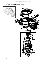
Page 52: ...5 8 5 Exploded Views and Parts List 5 5 SUMP ASS Y DMS500 400 300 301TR All manuals and user guides at all guides com ...

Page 53: ...10 SCREW TAPPING 2涋 TRS 4 10 3儆 ROHS 1 SNA 19 5121866000 DISTRIBUTOR SHAFT SEAL SILICON 1 SNA 20 5121827000 DISTRIBUTOR SHAFT POM F20 03 N109 LDS 1 SNA 21 5121826000 DISTRIBUTOR DISK POM F20 03 N109 LDS 1 SNA 22 F269 2190021000 DD81 01226A SYCHRONOUS MOTOR MOTOR SYCHRONOUS DMS400TRW XFA DMS400TUB 1 SA 23 3210074012 SCREW TAPPING 2涋 PAN 4ీ12 3儆 ROHS 2 SNA 24 F286 2160042001 DD81 01250A MICRO SWITCH...

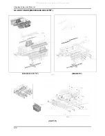
Page 54: ...5 10 5 Exploded Views and Parts List 5 6 ASSY RACK DMS500 400 300 301TR DMS500 400 301TR DMS300TR DMS TR 22 23 All manuals and user guides at all guides com ...

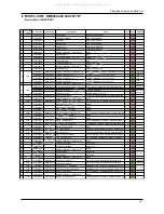
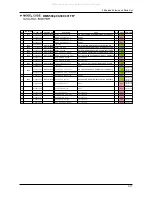
Page 55: ...TU 8 SA 10 5122447000 RACK HANDLE UPPER PP TALC30 1 SNA 11 5122448000 RACK HANDLE LOWER PP TALC30 1 SNA 12 F205 5122453000 DD82 01021A CUTRELY BASEKT ASS Y A S ASSY CUTRELY BASEKT DMS400TRW XFA DM SA 13 5122439000 WIRE TINE POM 1 SNA 5122434000 DD82 01019A UPPER RACK ASSY SS A S ASSY UPPER RACK DMS400TRW XFA DMS400 1 SA DMS500TR DMS400TR DMS301TR 5122434100 UPPER RACK ASSY SS HEBA2 SA DMS300TR 15 ...

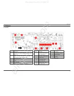
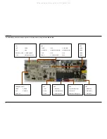
Page 56: ...6 Dispensor Circulation Pump Water softener Location Description 7 Sychronous motor Fan motor Electrical Safety Hose 8 Drain Pump Power AC1 AC2 9 Dispensor relay 10 Circulation Pump relay 11 Water softener relay 12 Sychronous motor relay 13 Fan motor relay Location Description 14 Electrical Safety Hose relay 15 Drain Pump relay 16 Main relay 17 Heater relay Y X Z _ X X XW XX XY XZ X X All manuals ...

Page 57: ...1 Flow meter out 12 5V CN9 1 GND 2 GND 3 GND 4 GND CN6 Micom Writer 1 GND 2 MODE 3 5V 4 OCDIO 5 OCDCK CN4 1 AC1 2 AC2 3 HPS CN3 1 Dispensor 2 Circulation Pump 3 Water Softener CN2 1 Sychronous motor 2 Fan motor 3 Electriacl Safety Hose CN1 1 Drain Pump 2 Power AC2 3 Power AC1 HWDLOHG 6SHFL FDWLRQV DQG HVFULSWLRQV IRU RQQHFWRUV DQG 5HOD THUPLQDOV 0 1 3 All manuals and user guides at all guides com ...

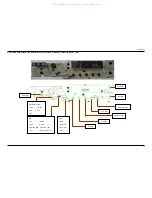
Page 58: ...1 Micom Writer 1 GND 2 Mode 3 5V 4 IO 5 CK Select S W Power S W Start S W Delay Start S W CN2 1 5V 2 GND 3 RXD 4 TXD 5 Wakeup_RXD 6 Wakeup_TXD 7 12V 8 Relay source 12V CN3 1 GND 2 Rinse S W 3 Door S W 4 12V 1 2 S W Sterilization S W Plus S W 4 in 1 S W All manuals and user guides at all guides com ...

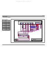
Page 59: ...r e b m u N t n e m u c o D e z i S t e e h S e t a D of 1 Designed by Dishwasher Development Team of Tong Yang Magic Circuit Diagram of DMS400 A 1 1 Tuesday January 05 2010 AC Part DC Part PCB M M M M AC 230V 50Hz 0 Noise Filter HPS HPS t THERMISTOR t THERMISTOR C Pump TP 135 C Pump TP 135 1 2 CN2 CN2 1 2 3 Heater TF 128 Heater TF 128 CN7 CN7 1 2 Flow Meter Flow Meter 1 2 1 2 CN3 CN3 1 2 3 Disrti...

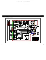
Page 60: ...8 1 8 Schematic Diagram 8 Schematic Diagram 8 1 MAIN CONTROL DMS500TR Ã This Document can not be used without Samsung s authorization All manuals and user guides at all guides com ...

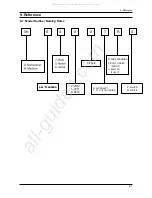
Page 61: ...ng Rules 0 2010 0 BASIC S 0 4 0 T R S 24 STANDARD S 24 STANDARD 4 1 2011 2 2012 T TY OUT SOURCING R R PROJECT R FREE STANDING U BUILT IN FULLY F BUILT UNDER FRONT S W WHITE S SILVER All manuals and user guides at all guides com a l l g u i d e s c o m ...

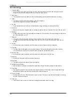
Page 62: ...QVH DLGV WR WKH LQVLGH RI WKH GLVKZDVKHU ZKHQ WKH DUH QHHGHG 7XE VV Q LQWHUQDO FDVH PDGH RI VWDLQOHVV VWHHO WKDW PDNHV XS WKH EDVLF IUDPHZRUN RI WKH GLVKZDVKHU 6XPS VV 7KH SODFH LQVLGH WKH GLVKZDVKHU ZKHUH ZDWHU LV FROOHFWHG 7KH LQMHFWHG ZDWHU JDWKHUV KHUH DIWHU FLUFXODWLRQ 7KH VXPS VV LV FRQQHFWHG WR WKH FLUFXODWLRQ PRWRU GUDLQ SXPS DQG GLVWULEXWRU PRWRU 7XE URQW VV Q LQWHUQDO FDVH PDGH RI VWDLQO...

Page 63: ...OLFDEOH QWHUQDWLRQDO DQG RU GRPHVWLF ODZ 631 OREDO 6HUYLFH 3DUWQHU 1HWZRUN UHD HE 6LWH 1RUWK PHULFD KWWS VHUYLFH VDPVXQJSRUWDO FRP DWLQ PHULFD KWWS ODWLQ VDPVXQJSRUWDO FRP CIS KWWS FLV VDPVXQJSRUWDO FRP Europe KWWS HXURSH VDPVXQJSRUWDO FRP China KWWS FKLQD VDPVXQJSRUWDO FRP VLD KWWS DVLD VDPVXQJSRUWDO FRP 0LGHDVW IULFD KWWS PHD VDPVXQJSRUWDO FRP All manuals and user guides at all guides com ...

Reviews: