background image

4. Troubleshooting

Error type

Error mode

Checking Method

Corrective actions

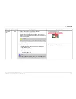
1) Check the connections for the Overflow Sensor connector.

Reconnect the Overflow Sensor connector.

2) Check whether the Inlet Valve operates normally

See “Water supply Error”.

3) Check whether water is supplied (even small amounts) in the intervals

when the Inlet Valve is not operating.

Remove foreign material from the Inlet Valve.

If you cannot remove the foreign material from the Inlet Valve,
replace it.

4) Check whether there is any trace of water leakage on the top of the Case

Sensor.

Clean the Hose-Sensor and the Case Sensor.

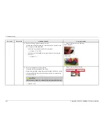
Over Level
Water Error

‘Heavy’ +

‘Quick’ LED

5) Check whether an “Over Level Water Error” is detected when the assy

wire-harness connector for Overflow Sensor is not connected.

Normal: The “Over Level Water Error” does not occur.

Faulty: Replace the Main PBA assy.

Nomral: Replace the Flow Meter.

4-9

Copyright© 1995-2010 SAMSUNG. All rights reserved.

Summary of Contents for DMT300 Series

Page 1: ... DMT300RFW XAC DMT300RFW XAC SERVICEMANUAL DISHWASHER Contents 1 Safety Instructions 2 Features and Specifications 3 Disassembly and Reassembly 4 Troubleshooting 5 PCB Diagram 6 Wiring Diagram 7 Schematic Diagram 8 Reference Refer to the service manual in the GSPN see the rear cover for more information ...

Page 2: ...butor Motor 3 9 3 2 6 Leakage Sensor 3 10 3 2 7 Panel Control Main PCB 3 10 3 2 8 Dispenser 3 13 3 2 9 Fan Motor 3 14 3 2 10 Case Sensor 3 16 3 2 11 Inlet Valve Flow Meter 3 17 3 2 12 Relay 3 19 3 3 Checkpoints after Finishing a Service 3 20 4 Troubleshooting 4 1 4 1 Information code 4 1 4 2 Service Inspection Mode 4 3 5 PCB Diagram 5 1 5 1 Main PCB 5 1 5 2 New PBA Detailed Specifications and Desc...

Page 3: ...er outlet at the same time There is a risk of fire due to overheating When removing the power cord make sure to hold the power plug when pulling the plug from the outlet Failing to do so may damage the plug and result in fire or electric shock When the dishwasher is not being used make sure to disconnect the circuit breaker or power cable from the power outlet Failing to do so may result in electr...

Page 4: ... tracking Make sure to discharge the PBA power terminals before starting the service Failing to do so may result in a high voltage electric shock When replacing the heater make sure to fasten the holder heater after ensuring that it is inserted into the bracket heater If not inserted into the bracket heater it touches the tub and causes noise and electric leakage During Servicing e eCAUTION When w...

Page 5: ... three times around the tap If you connect the grounding wire to a copperplate bury it 75 cm under the earth in a place with a lot of moisture NOTE Do not connect the grounding wire to a gas pipe plastic water pipe or telephone wire There is a risk of electric shock or explosion e eCAUTION Check the assembled status of the parts They must be the same as before servicing Check the insulation resist...

Page 6: ...e quieter than ever Self cleaning filter Cleaning the filter yourself is a thing of the past This product keeps food waste internally while operating then drains it automatically with the water Smart Digital leakage sensor Samsung dishwasher is equipped with a unique Digital Leakage Sensor designed to detect even the smallest traces of water Located below the dishwasher the sensor immediately shut...

Page 7: ...ash type Rotating nozzle spray Dry type Air vent dry system Power usage Main Motor 185W Heater 1100W Standard amount of used water 3 9 7 9 gallon 14 7 30ℓ Normal Cycle Size W D H 23 x 24 x 33 inch 605 x 627 x 860 mm e e ª ª e e ª ª ª ª µ µ ª ª ª ª ª ª e e ª ª µ µ e e ª ª e e ª ª ª ª e e ª ª µ µ µ µ ª ª e e ª ª e e º º ª ª e e ª ª NOTE Above images might differ in the dishwasher models Copyright 19...

Page 8: ... Handle STS Black White STS Black White Cover Handle X X X Cr Black Cr Cover Front L Silver Black White Silver Black White Functional Specifications Soil Detection Sensors O O O O O O Drying method Air vent Air vent Air vent Condensing Condensing Condensing Basket Height Adjustment 2 stage 2 stage 2 stage 2 stage 2 stage 2 stage Half Load X X X X X X Child Lock O O O O O O Sanitize O O O O O O Lea...

Page 9: ...op mounting Bracket install Screw DD94 01002A 2 2 Screw for side mounting 2 User Manual 1 Installation Guide DD68 00027A 1 Provided with the dishwasher Elbow 1 Water Supply Line Flexible STS supply line is recommend 1 Air Gap 1 Rubber Connector 1 Hose Clamp 1 Strain Relief 1 Sold separately Copyright 1995 2010 SAMSUNG All rights reserved 2 4 ...

Page 10: ...Screwdriver Philips flat Torx T20 Preparation for parts replacement 1 Take out the residual water inside the product Drain the water by operating the drain pump 2 Close the water supply valve 3 Turn off the power disconnect power cable You must turn off the circuit breaker connected to the product 4 Pull out the unit from the sink and lay it on the floor Be careful of the drain hose when pulling o...

Page 11: ...e the two 2 screws that hold the base and the shutter in place 2 Remove the leakage sensor connector white inside the shutter 3 Disconnect the wire terminal blue connected to the thermistor 4 Check the location of the thermistor and remove the two 2 screws that hold the thermistor to the case sump Copyright 1995 2010 SAMSUNG All rights reserved 3 2 ...

Page 12: ...Hold the nozzle duct and remove it carefully To remove it smoothly remove the hooks clamping the bracket duct U using a flat screwdriver and remove the hooks clamping the bracket duct M Pull them out while rotating them to the left 4 Remove the cover heater from the sump assy You will need a flat screwdriver for the removal To remove a hook from the cover heater insert the end of the screwdriver i...

Page 13: ...tter 7 Remove the two 2 terminals which are inserted into the heater Do not pull the wire Remove it by holding the metallic part at the end of the wire 8 Remove the two 2 holder heaters which are connected to the heater by rotating them counterclockwise 9 Place the dishwasher the right way up again Open the door and hold and remove the heater CAUTION The heater may be very hot Make sure to check i...

Page 14: ...the shutter in place 2 Remove the leakage sensor connector white in the shutter 3 Disconnect the two 2 drain pump connectors 4 Remove the drain pump by rotating it counterclockwise When removing the drain pump lift up the hook holding it in place slightly and then rotate it so that the hook is not damaged 3 5 Copyright 1995 2010 SAMSUNG All rights reserved ...

Page 15: ...le and remove it Place the removed lower nozzle in a safe location along with the baskets 3 Hold the nozzle duct and remove it carefully To remove it smoothly remove the hooks clamping the bracket duct U using a flat screwdriver and remove the hooks clamping the bracket duct M Pull them out while rotating them to the left 4 Remove the sump assy Remove the ten 10 screws on the assy filter mesh Exce...

Page 16: ...on motor to the shaft Use your hand to hold the impeller circulation and turn the screw CAUTION Turn the screw clockwise to remove it 7 Remove the valve distributor Remove the seal distributor CAUTION Make sure to check whether any water is left Remove any remaining water to prevent water leakages while servicing 8 Remove the case scroll Check if the seal rubber scroll is normal If it is damaged o...

Page 17: ...e and the shutter in place 11 Remove the leakage sensor connector white inside the shutter 12 Remove the circulation motor connector white 13 Remove the five 5 screws holding the circulation motor and the sump in place 14 Hold and pull the circulation motor to remove it from the sump Copyright 1995 2010 SAMSUNG All rights reserved 3 8 ...

Page 18: ...eakage sensor connector white inside the shutter 3 Remove the two 2 distributor motor connectors 4 Remove the two 2 screws that hold the distributor motor in place You can remove one of the two screws through the hole in the base Pull the distributor motor out CAUTION Be careful removing because it is combine with rubber seal and distributor valve 3 9 Copyright 1995 2010 SAMSUNG All rights reserve...

Page 19: ...e 3 2 7 Panel Control Main PCB 1 Open the door completely Remove the twelve 12 screws holding the tub front frame front and panel control in place CAUTION Before removing the screws place a cushioned mat on the floor to prevent the handle and frame front from being scratched After removing them make sure to hold the tub front with your hand while you are working as the tub may close and harm you C...

Page 20: ...e the panel control by holding and pulling it And you can remove and replace the door lock switch in this step Remove both connectors of door lock switch 4 Remove the four 4 screws holding the PCB assy and panel control in place Remove all the connectors connected to the PCB assy 5 You can remove the PCB assy 6 Remove the three 3 screws holding the PCB tact assy and panel control in place 3 11 Cop...

Page 21: ...3 Disassembly and Reassembly 7 You can remove the PCB tact assy Copyright 1995 2010 SAMSUNG All rights reserved 3 12 ...

Page 22: ...ront with your hand while you are working as the tub may close and harm you CAUTION Do not place the removed screws on the tub front They may fall into the sump assy 2 Remove the fan motor thermal actuator connectors 3 Remove the four 4 connectors on both sides of the dispenser CAUTION The connectors are of the locking type and are hard to remove Be careful not to break them when removing them 4 R...

Page 23: ...e CAUTION Before removing the screws place a cushioned mat on the floor to prevent the handle and frame front from being scratched After removing them make sure to hold the tub front with your hand while you are working as the tub may close and harm you CAUTION Do not place the removed screws on the tub front They may fall into the sump assy 2 Remove the fan motor thermal actuator connectors 3 Rem...

Page 24: ...crews holding the cover fan in place 6 Hold and remove both the case vent assy which are located at the front of the tub front 7 Remove the fan motor from the case vent assy It is connected with two 2 screws and the fan vent is inserted into the shaft of the fan motor Remove the screws first and carefully pull out the fan motor 8 Release the three 3 screws at side of case vent 3 15 Copyright 1995 ...

Page 25: ...e they are connected with a hook 10 Detaching the cave vent 11 Remove the fan vent and gasket vent 3 2 10 Case Sensor 1 Remove the two 2 screws of the L frame 2 Remove the L frame CAUTION Make sure to wear gloves when removing the L frame Be careful as the steel plate may harm you Copyright 1995 2010 SAMSUNG All rights reserved 3 16 ...

Page 26: ...m the case brake assy Be careful to avoid breaking them because they are connected with a hook 6 Separate the case sensor assy into the case sensor and the cover sensor assy Be careful to avoid breaking them because they are connected with a hook 7 Remove the pole sensor from the cover sensor assy 8 Remove the micro switch which is fixed by a hook of the cover sensor assy Disconnect the micro swit...

Page 27: ...rews unfasten it a little in the clockwise direction and remove the screws 4 Remove the two 2 screws and ground wire screw from the inlet valve 5 Hold and lift up the inlet valve and release flow meter s clasp on the bottom of the base CAUTION When release flow meter s clasp push up using tool 6 Pull out the inlet valve until the hose clamp can be removed and remove the clamp and hose CAUTION Take...

Page 28: ...screw the two 2 screws connecting the Frame R 2 When you separate the Frame R you can check the Relay 3 Separate the terminal of Relay Unscrew the screws of relay using short body screwdriver CAUTION If reassemble the terminal of Relay after check or replacement you must be careful Don t confuse CAUTION Reassembly is in the reverse order of the removal 3 19 Copyright 1995 2010 SAMSUNG All rights r...

Page 29: ...ether they are fastened with the specified torque 5 Remove foreign material Check whether any foreign material such as soil wire scraps and screws are in the dishwasher Check whether any foreign material is entering through the sump into the disposer 6 Check for water leakage Check whether there is water leakage from the hose connector door case sump drain motor circulation motor heater thermistor...

Page 30: ...umes after Low Level is detected for the 1st time Low Level Sensor terminal not connected Possible defect Low Level Sensor Main PBA Water supply error 1 When the pulse of 100 or less is detected even 1 minute after the water supply 2 When flow meter pulse is 5 or less 5 seconds after the water supply starts 3 When the water supply does not occur 5 minutes after the water supply starts Alien partic...

Page 31: ... part leakage Possible defect Flow Meter Main PBA Leakage error When leakage sensor detects 4 5V or below for 1 seconds Possible defect Base part hose connection Sump and Tub assembly Drain Pump assembly Main PBA Button error When the button is pressed continuously for over 30 seconds Possible defect Sub PBA Main PBA Door open warnning When door is open in washing period Door is not close properly...

Page 32: ...at first If water is not supplied Water Supply Error Quick LED will blink When water level is low after water is supplied Low Level Water Error Normal Heavy Quick LED will blink When Turbidity problem is detected after water is supplied Normal Heavy Delicate LED will blink If all functions in this mode are completed Wash LED will blink No 2 Delicate LED Circulation Motor A nozzle does not inject w...

Page 33: ...lation Motor On Heavy LED On Off Heavy LED Off Fan Motor On Heavy LED On Off Heavy LED Off Drain Pump On Heavy LED On Off Heavy LED Off When Delicate button is pressed it woks Heater On Delicate LED On during 2 seconds When a different button is pressed during individual operation of the operating part operating part is stopped and the applicable operation for the pressed button s function will st...

Page 34: ... voltage between the white wire of the Main PBA CN101 connector and the brown wire of the CN201 Normal 120V while operating Faulty Replace the Main PBA assy Normal Replace the Inlet Valve Remove Retainer Check voltage 7 Check the Power Relay See the Power Relay error 8 Check whether the water supply stops after water is supplied for 5 seconds Replace the Flow Meter 9 Check whether the water supply...

Page 35: ...w Level Sensor See the Low Level Water Error 3 Check the connections for the Drain Pump connector Reconnect the Drain Pump connector 4 Check whether the Drain Pump coil is conductive Remove the connector before measuring Normal Approx 25Ω Faulty Replace the Drain Pump 5 Check the operation of the Drain Pump Relay Check the operating voltage between the white wire of the Main PBA CN101 connector an...

Page 36: ...is condensation on the Main PBA connector CN803 Faulty Remove any condensation and moisture Normal Replace the Control Panel assy Error type Error mode Checking Method Corrective actions 1 Check the connections of the Heater connectors Reconnect the Heater connectors 2 Check the resistance between both ends of the Heater Check the resistance between both ends of the Heater directly or check the re...

Page 37: ...pin 2 red of the CN302 connector When the Heater is off 9 5 to 12 5V When the Heater is operating 0 5V Faulty Replace the Main PBA assy Normal Replace the Heater Relay Remove Retainer Check voltage Error type Error mode Checking Method Corrective actions 1 Check the hot water connections for the Inlet Valve See the Temperature Sensor Error High Temperature Heating Error Normal Quick LED 2 Check th...

Page 38: ...reign material from the Inlet Valve If you cannot remove the foreign material from the Inlet Valve replace it 4 Check whether there is any trace of water leakage on the top of the Case Sensor Clean the Hose Sensor and the Case Sensor Over Level Water Error Heavy Quick LED 5 Check whether an Over Level Water Error is detected when the assy wire harness connector for Overflow Sensor is not connected...

Page 39: ...he voltage between both ends of the Thermistor Normal 0 2 to 4 5V Measure the resistance between both ends of the Thermistor Remove the connector before measuring See the Table right THERMISTOR TABLE Temp ºC Resistance kΩ 5 125 780 10 98 323 15 77 454 20 61 465 25 49 120 30 39 517 35 31 996 40 26 065 45 21 358 50 17 599 55 14 579 60 12 140 65 10 159 70 8 542 Faulty Replace the Thermistor Nomral Re...

Page 40: ...AC 120V Connect to a 120V power source 3 Check the wires of the Main PBA power part Measure the voltage between the black wire and the white wire of CN101 Nomral AC 120V Faulty Check and replace the wires of the power part Remove Retainer Check voltage Power error None 4 Check the DC voltage of the Main PBA See Main PBA DC voltage error 4 11 Copyright 1995 2010 SAMSUNG All rights reserved ...

Page 41: ...onnector and pin 7 pink of the CN302 connector Normal 4 5V to 5 5V Measure the voltage between pin 6 amber of the main PBA CN302 connector and pin 9 white of the CN302 connector Normal Power Key On 9 5V to 12 5V Normal Power Key Off 5 5V to 7 0V Faulty Replace the Main PBA Assy Remove Retainer Check voltage 4 5V 5 5V Check voltage 9 5V 12 5V or 5 5V 7 0V Copyright 1995 2010 SAMSUNG All rights rese...

Page 42: ...onnector before measuring Normal Approx 14 2 Ω Faulty Replace the Circulation Motor 4 Check the operation of the Circulation Motor Relay Check the operating voltage between the white wire of the CN101 connector and the red wire of the CN201 connector Normal 120V while operating Faulty Replace the Main PBA assy Normal Replace the Circulation Motor Remove Retainer Remove Retainer Check voltage The n...

Page 43: ... door is closed Faulty Replace the Door Sensing Switch Normal Replace the Main PBA assy 1 Check whether the nozzle injects water normally See The nozzle does not inject water No Washing None 2 Check the operation of the Heater See Heater Error Error type Error mode Checking Method Corrective actions 1 Check the connections for the Door Sensing Switch Check the blue wire and the switch connected to...

Page 44: ...re the voltage between pin 6 amber of the main PBA CN7 connector and pin 7 pink of the CN7 connector Normal 4 5V to 5 5V Measure the voltage between pin 6 amber of the main PBA CN7 connector and pin 9 white of the CN7 connector Normal 10 5V to 13 0V New PBA Check the DC voltage of the Main PBA Measure the voltage between pin 6 amber of the main PBA CN302 connector and pin 7 pink of the CN302 conne...

Page 45: ... Relay and the Heater Relay Normal 120V Reconnect the Power Relay Power Relay Terminal wire Yellow Amber wire Heater Relay Terminal Black wire Black wire 2 Check the door switch Check the white wire and the switch connected to the white wire When the door is open The Door Switch is OFF When the door is closed The Door Switch is ON NOTE The Power Relay and the Heater Relay use a 12V line If the swi...

Page 46: ...mal 2 V Faulty Replace the main PBA assy Remove Retainer Check voltage 4 Check the operation of the Power Relay Start the cycle by pressing the Power Key Measure the operation voltage between the terminal black wire black wire of the Heater Relay and the terminal yellow wire amber wire of the Power Relay CAUTION Check the color of the wires of the Power Relay and the Heater Relay Nomral 120V Fault...

Page 47: ...or 3 Check the resistance of the Dispenser Remove the connector before measuring Normal Approx 2 3 kΩ Faulty Replace the Dispenser Detergent is not dispensed None 4 Check the operation of the Dispenser Relay Check the operating voltage between the white wire of the CN101 connector and the white wire of the CN201 connector Normal 120V while operating Faulty Replace the Main PBA assy Remove Retainer...

Page 48: ...e the connector before measuring Normal Approx 150 Ω Faulty Replace the Fan Motor assy 4 Check the resistance of the Thermal Actuator Remove the connector before measuring Normal Approx 1 45 kΩ Faulty Replace the Thermal Actuator 5 Check the operation of the Fan Motor Relay Check the operating voltage between the white wire of the C101 Normal 120V while operating Faulty Replace the Main PBA assy R...

Page 49: ... See Detergent is not dispensed Error type Error mode Checking Method Corrective actions 1 Check the connections for the Sub PBA connector Reconnect the Sub PBA connectors 2 Check the LED and Input Key 1 Push Normal Heavy Power Key 2 Push Normal Key 4 times 3 Push all key except Start Pause Key Normal All LED is light Faulty Replace the Sub PBA LED or Input Key Fail None 3 Check the DC voltage of ...

Page 50: ...verflow Sensor Cold Water Counter Leakage Sensor Temperature sensor Door Sensor 4 NC 5 Dispensor Driving Relay 6 Drain Pump Driving Relay Location Description 7 Inlet Valve Driving Relay 8 Circulation Wash Motor Driving Relay 9 Vent Motor Driving Relay 10 Electric Driving Connector 11 Micom Writer Connector 12 NC 13 NC Location Description 14 NC 15 Tact button LED Driving 5V DC GND 16 NC 17 NC 18 ...

Page 51: ...r 6 Leakage Sensor 7 NC 8 Thermistor 9 DC 12V 10 Door Checker Receiver CN701 Micom Writer 1 DC GND 2 MODE 3 DC 5V 4 OCKIO 5 OCDCK CN101 3 PBA Power 120V Black Wire 2 NC 1 PBA Power 120V White Wire CN302 1 Power Relay Driver 2 Heater Relay Driver 3 Half Load Sensor 4 Turbidity Receiver 5 Turbidity Transmitter 6 DC GND 7 DC 12V 8 Rinse Sensor 9 DC 12V CN803 1 LED_1 2 LED_2 3 LED_3 4 LED_4 5 LED_5 6 ...

Page 52: ... n x x u u v v m m n n v v u u v v m m n n w w u u v v m m n n e e e e e e e e e e e e e e e e v v v v w w w w e e v v w w v v w w w w x x v v w w x x v v w w v v w w v v v v w w v v w w w w x x v v w w x x v v v v w w t t w w v v w w v v v v v v t t v v w w x x y y z z z z y y x x w w v v v v v v v vv v v v v v u u u u e e e em m n n e e x x y y z z v v w w w w w w v v v v x x x x y y z z v v y y...

Page 53: ...2K R306 KRC246 TR202 2K 10D471 PC817 4 3 1 2 470V ZNR101 100 R508 PC102 100nF C305 100nF C306 2K R314 1K R313 51K R108 IC104 7033P 100 R511 1K R302 R513 100 OJ105 100 R502 5V 100 R504 R503 100 200K R305 R304 10K 51K R119 R303 200K 1 2M R101 5V C108 10uF 5V 2K R601 5V 2K R111 D208 MM4148 TR507 KRA225S TR509 KRA225S TR511 KRA225S 100nF C302 R505 100 100 R506 ZD101 R507 100 MTZ10B 100nF C104 D201 1K ...

Page 54: ...r Naming Rules DMT D Dishwasher M Machine T 24 Tall Tub 3 0 0 R F S 7 8 Best 5 6 Better 3 4 Good 0 2010y 1 2011y 2 2012y R R pjt 0 Basic 1 Ver 1 H Hidden F Front S Stainless B Black W White 8 1 Copyright 1995 2010 SAMSUNG All rights reserved ...

Page 55: ...e aids are stored so they can be used by the dishwasher The dispenser automatically supplies detergent and rinse aids to the inside of the dishwasher when they are needed 8 Tub Assy An internal case made of stainless steel that makes up the basic framework of the dishwasher 9 Sump Assy The place inside the dishwasher where water is collected The injected water gathers here after circulation The su...

Page 56: ...is open or closed If the door is open while the dishwasher is running the cycle is temporary stopped 16 Child Lock This function is used to prevent a child from operating the dishwasher while it is running 8 3 Copyright 1995 2010 SAMSUNG All rights reserved ...

Page 57: ...urope samsungportal com China http china samsungportal com Asia http asia samsungportal com Mideast Africa http mea samsungportal com This Service Manual is a property of Samsung Electronics Co Ltd Any unauthorized use of Manual can be punished under applicable International and or domestic law 2010 Samsung Electronics Co Ltd All rights reserved Printed in Korea Code No DD68 00008A ...

Reviews: